How can I fix problems in components that I’ve made.

Happy holidays everyone!!
I'll be grateful to those who can help me to avoid what I am doing wrong.
I am assuming the following:
1.) I 've raised arguments that I believe are not consistent with the spirit of BRICSCAD, so I seek the help of this forum to put the ideas in order.
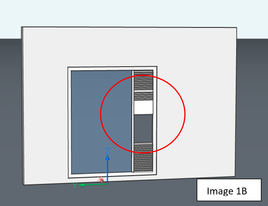
The distance constraints implies, that when placing a dimension for width and height, for example, a Window measures W = 2.50 meters, H = 1.50 meters, and when trying to make that dimension greater than the Constraint W x H, the component is altered, This happens if there are elements that are repeat, for example the blinds of a window. Images 1A/1B
This window has the range to change its height from 1.80 meters to 1.00 meters, outside of this range the component does not work well.
In relation to the width of the window the minimum width can be 0.50 meters (500 millimeters)
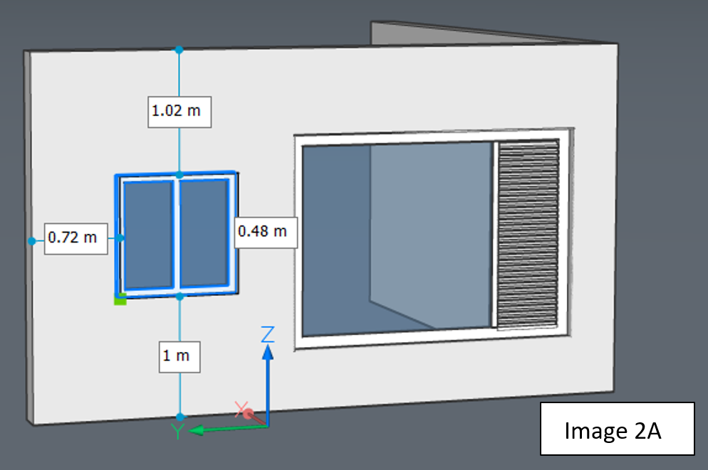
2.) The component does not display dimensions, (the one on the right), like the original component, (the one on the left) Images 2A/2B
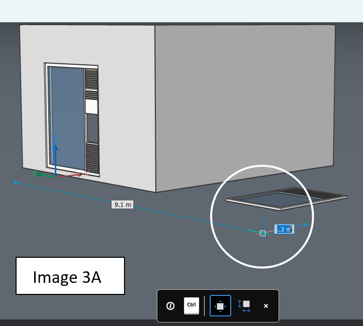
3). The insertion point is not consistent before the component insertion. Image 3A
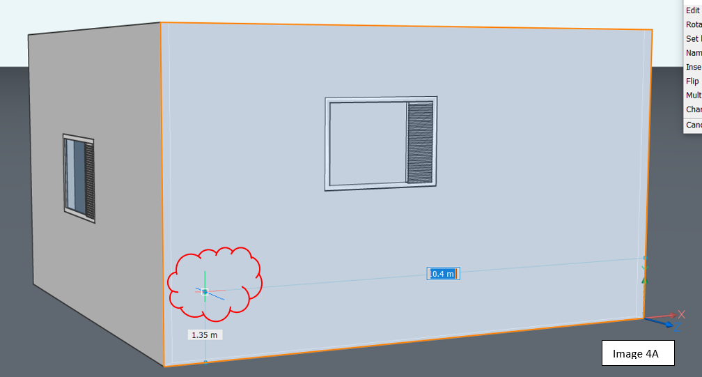
4.) How can I fix the insertion point and the dynamic input options with de control key? Image 4A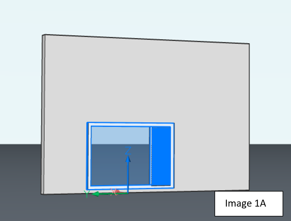

and finally
How can I create the parameter for the depth of the frame respect to the exterior or interior face of the wall?.
Thanks in advance.
Comments
-
@Joseph_Brown said:
Happy holidays everyone!!
I'll be grateful to those who can help me to avoid what I am doing wrong.I am assuming the following:
1.) I 've raised arguments that I believe are not consistent with the spirit of BRICSCAD, so I seek the help of this forum to put the ideas in order.The distance constraints implies, that when placing a dimension for width and height, for example, a Window measures W = 2.50 meters, H = 1.50 meters, and when trying to make that dimension greater than the Constraint W x H, the component is altered, This happens if there are elements that are repeat, for example the blinds of a window. Images 1A/1B
This window has the range to change its height from 1.80 meters to 1.00 meters, outside of this range the component does not work well.
In relation to the width of the window the minimum width can be 0.50 meters (500 millimeters)I'll have to look at your file later, but this sounds like you put in another constraint that somehow interferes with the W and H constraints when you exceed certain values.
Another thing that may be happening is that constraints of the same type are moving in opposite directions of some parts, it depends on the order in which point you select first and then select second.
In the past for some objects selecting the top face first and then the bottom face would cause the top faceto move when changing the distance constraint value. For other objects however you had to switch the order of selection, i..e bottom first and then top face in order to make the top face move instead of the bottom face. This is supposed to be corrected but I'll have to check. One way to solve this is to fix the face that should remain in place and thus force the other face to move.2.) The component does not display dimensions, (the one on the right), like the original component, (the one on the left) Images 2A/2B
I'll have to look at this later as well.
3). The insertion point is not consistent before the component insertion. Image 3A
Two things to keep in mind:
1. The insertion point of the objection you are trying to insert? In that case make sure the objects origin or the point on the to be inserted object is located at x,y,z=0,0,0.
2. Make sure the Z orientations match in both the object you are inserting and in your workspace, i.e. when creating the parametric object you have to decide which plane will the in the x,y plane and which direction the positive Z axis is pointing to. If this varies between parametric objections you will get seemingly inconsistent behaviour while it is actually behaving properly. In other words, when creating parametric objects try to be as consistent as you possibly can.4.) How can I fix the insertion point and the dynamic input options with de control key?
Assuming this is about the insertion of an object, see my comments under point 3.
and finally
How can I create the parameter for the depth of the frame respect to the exterior or interior face of the wall?.This will have to be done afterwards by manually creating a distance constraint between the wall surface and the object you inserted. Depending what you want to use as reference point you can do with one constraint or you may have to create additional constraints.
E.g. you could set a distance constraint between the inner surface of the wall to the surface of the object that is on the inside as well (though it could be the center or outside surface of the object, depending on how you want to define things).The "problem" with constraints is to be careful to put in no more constraints than you absolutely need to make it work correctly, the more constraints you have the more chance there is for them to get in each others way and get stuck or get things you don't want to happen. E.g. Solidworks has the habit of nagging that objects are not fully defined (parametrized) but doing that may cause things to get stuck an your only solution is sometimes to remove all constraints and start over.
0