Corridor - applying super elevation

Hi
Is it possible to apply superelevation to curves in V21 Civil? Currently I am working around this issue by applying templates with different cross falls at discrete stations. To create a design surface I extract 3d poly lines from the corridor and join them up manually with 3d lines and then triangulate the lot. If it were possible to automatically transition between templates it would speed things up.
Cheers
Brian
Comments
-
Does somebody have new experiences?
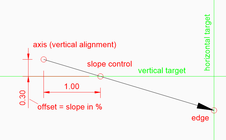
My idea is to control the slope by having a control point in the section template. The control point is attached to a vertical target and the x-distance between axis and control point is fix.
Further there is another point for the edge of the road. The edge point is constraint by “angle and distance x”. Base point is the axis point and reference point is the point for slope control. The angle is set to 0 degrees. If the slope control point is moving up or down by following the target, the edge point will follow in correct slope no matter how wide the road is.
Now the tricky part… how to get a vertical target for the slope control?
I have two ideas.
1. Beside my vertical alignment for the axis I draw an additionally one in the same vertical alignment view. This leads to a second 3d-alignment witch can be used as vertical target for the slope control. Best to have the additionally alignments on a separate layer. The second alignment should have the same parameter as the one for the axis. If both alignments match each other, you get a road with no cross slope. If you want a specific slops at various stations, you must edit the elevation of the second vertical alignment or add new points.
The problem: You have to worry about more than one vertical alignment per road. And the geometry is maybe not correct because of the fillets.
2. I attach a grading to the 3d-alignment. Then separate the grading in several regions. Here I can define the slope at every station. If this is done, I extract the border of the grading. I get a 3D-polyline. I can now explode it and use one side as vertical target for the slope control.
The problem: It is not associative. If I change the cross slope I must extract again. I also don’t know if the transitions are ok.
Maybe it could be an option to draw a Cross slop data band made of vertical alignments directly in the vertical alignment view. And then connect it somehow😅 to the slope control.
Does someone have another idea how to deal with it? Maybe using parameter inside the section template?
 0
0 -
One of the advantages in "Civil Site design: is the ability to individually on a vertical basis design a string joining to others in you cross section template so can change the vertical control within a chainage range, it also supports horizontal alignments, think of a road widening at grade for a turning slot at 3% slope
There is multiple control variations built in to the software and runs within Bricscad. Sounds like what your looking for.
Have a look at these in the driveway video at end can see result in full 3D. There is a video of the 1st image showing how it was put together rather amazing to see it all come together.
0