3D model and length/thickness issue

Hi,
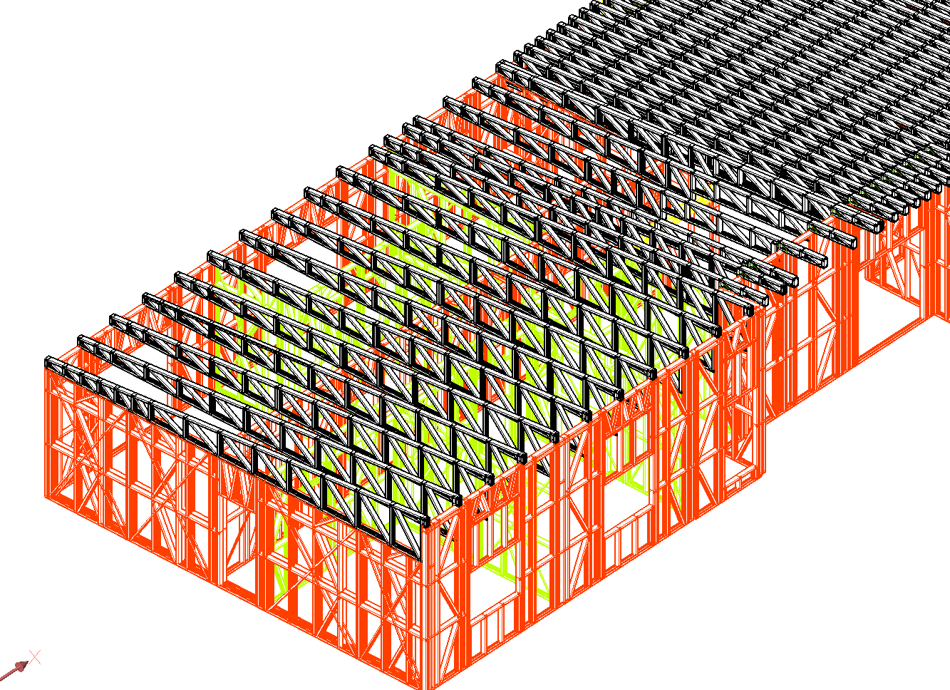
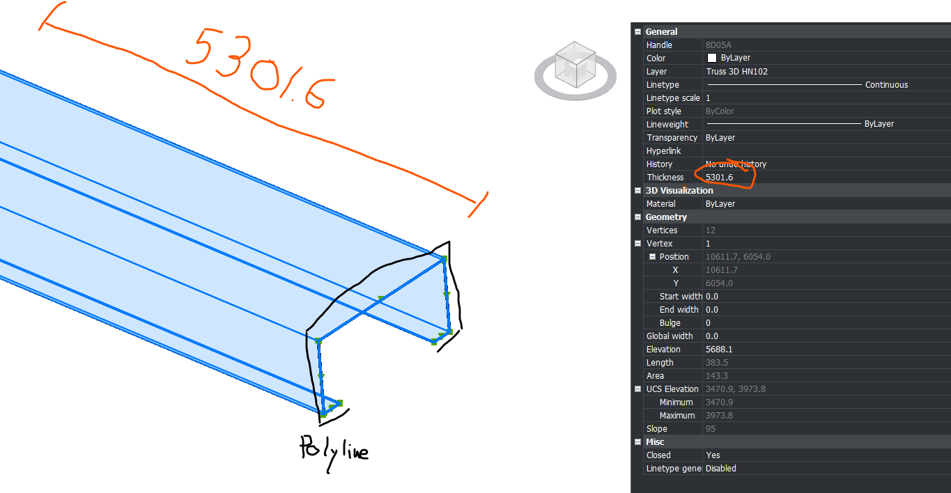
I receive 3D model from a truss supplier that looks like the screenshot attached. My issue is that each part is a polyline for which the length of the member is the thickness of the polyline.
Is there a way to convert it so that I have a line/polyline that is simply the length of the member? Or rebuild a different model ?Like this I could import the 3D model in Staad Pro and save a lot of time!
Thanks!
Comments
-
Man that is weird
0 -
Fantastic. This 3D model was created by a true dark genius. Ha-ha.
I once encountered such projects and added a function to the AVC MeshToSolid ( ) command to convert polylines with thickness to solids. But even this function won't work in your case simply because the polyline isn't closed, and you won't get a closed volume.Theoretically, you could try converting these polylines to surfaces. Then you could try using BricsCAD Mechanical to use these surfaces as sheet metal.
If you have a lot of such drawings and need automation, I could further develop the MeshToSolid plugin to convert polylines to surfaces. Write to me if you are interested and ready to pay for the revision.
Basically, you could create a simple script that would simply draw a line from the starting point of each polyline in the direction of the polyline's normal and with a length equal to the Thickness property. It's literally three lines of code.1 -
I like the idea of making a polyline with a length equal to thickness. It may create few inconsistencies where all members join, but it may work good.
0 -
The issue is to get the thickness direction as suggested. Once that is known can draw a single pline based on 2 pts of XYZ. Had a quick play, in image made a shape gave it a thickness so was thickness in Z direction. The second was same pline but rotated 30 around Y axis.
Ok now maybe the easy part, the true vertical the dxf code 210 = (210 0.0 0.0 1.0), the rotated 30 gives = (210 0.5 0.0 0.866025403784439) so the 210 dxf is a XYZ direction. take say 1st point in pline then workout a new 3d point as 2nd point, then draw a line or pline based on thickness.
Never done stuff with 210 so will investigate, some one else may have something for the point in world XYZ and angles.
Ok throw all that away,
UCS OBJ pick pline
LINE 0,0,0 0,0,thickness Enter
Do again
I have not coded anything but need you provide a sample dwg with 20 objects at most for testing. Make sure my idea is correct.
0 -
Looks like the Profile Curve is closed (?)
Does none of Convert to Solid or Solidify work ?
Or do you only want 3D Lines from the length of the "Extrusion"I am not really sure what your expected outcome should be.
Or what the source file was. Exported as a DWG ?
Could it also be exported as an IFC ?Could you copy a handful of these parts into a blank file and attach it here ?
0 -
As others have stated, a sample drawing would be useful to understand what you're dealing with. Based on the OP screengrab it looks like the members are created from a closed 2D Polyline (to describe the profile) with thickness assigned to define the member length.
Assuming this is the case, then the attached LISP will convert these type of polylines to 3D solids. Essentially converts the drawing to a 3D solid model.
Whether this is something that an application like Staad Pro can work with, I don't know. Again you would need to provide more detail or an example of your typical output to it.
If you have BricsCAD BIM, then perhaps try using BIMIFY to convert the 3D Solids to a BIM model, then use BIMANALYTICALMODEL to in turn create an analytical model that you can export to use in your structural app.
Jason Bourhill
CAD Concepts Ltd
0 -
I tried putting the following query in to the new BricsCAD AI Assistant.
Convert a polyline profile with thickness to a 3d solid.and got the following response:
You can convert a closed polyline with non-zero thickness and uniform width into a 3D solid using the CONVTOSOLID command. This command is available in all BricsCAD versions.
To use this command:
- Type CONVTOSOLID in the command line and press Enter.
- Select the polyline you want to convert.
- Press Enter to complete the command.
Alternatively, you can use the EXTRUDE command on a closed 2D polyline (with zero thickness) to create a 3D solid by specifying an extrusion height. This command is available in BricsCAD Pro and higher.
******************************************************************
Clearly should of checked this first! CONVTOSOLID gives the same results as the LISP I posted previously. If you prefer a mesh entity, then you can use CONVTOMESH instead, and if your polyline isn't a closed profile, then you can use CONVTOSURFACE.
Jason Bourhill
CAD Concepts Ltd
1 -
Just for your information: after researching this topic, I modified the AVC MeshToSolid plugin. Now it converts all curves into solids if the Thickness and Global Width are specified. If the Width is zero and the polyline is not closed, it creates surfaces. This means that when the plugin version is published, you'll be able to use a single command to convert any object into a fully functional solid model. I hope this will be more convenient than using several different commands and scripts.
0 -
Still waiting for Manu25 for a sample dwg. In 1st post question was "get length", so if converted to a solid how do you get length ? Not sure can use massprop to get the length it appears to not return a height based on a rotated solid object, simple to check.
Vertical
Lower Bound: X= 0.29 Y= -7.283 Z= 0
Upper Bound: X= 7.157 Y= -0.416 Z= 50Rotated
Lower Bound: X= 0.75 Y= -7.283 Z= -1.717
Upper Bound: X= 31.697 Y= -0.416 Z= 45.018A question to @Manu25 why get length ? Truss manufacturer takes care of that.
0 -
Hi,
Greetings!Yeah, this is pretty common with truss models coming from fabrication or detailing software—they’re usually exported as “thick” polylines or extruded profiles instead of centerlines, which makes analysis tools like STAAD a pain.
What you’re seeing is basically each member represented as a closed polyline (or 3D polyline) with a width/thickness, instead of a simple line along the member axis.
Here are a few practical ways to handle it:
1. Extract centerlines (best approach)
If your polylines are consistent, you can:- Use
PEDIT→ Convert to polyline (if needed) - Then try
OVERKILLto clean duplicates - After that, use
CENTERLINE(if geometry allows) or manually snap midpoints
But honestly, for trusses, this only works cleanly if geometry is simple.
2. Use “Extract Edges” trick
If these are actually 3D objects (not just polylines):- Run
XEDGES(Extract Edges) - Then isolate the edges that represent the member axis
- Clean up using
OVERKILL
This sometimes gives usable lines, but depends on how the model was built.
3. Convert via Dynamo / scripting (if you have Revit workflow)
Since you’re working toward STAAD:- Import DWG into Revit
- Use Dynamo to detect centroids of members and generate analytical lines
- Export to STAAD (via CIS/IFC or direct plugins)
This is much faster if you deal with these files regularly.
4. Ask supplier for centerline model (honestly the best option)
If possible, request:- Analytical model / stick model
- Or even IFC with analytical lines
Most truss software (MiTek, Alpine, etc.) can export this, but they don’t by default.
5. Semi-manual quick method (works surprisingly well)
If spacing is repetitive like your screenshot:- Snap midpoints of end faces
- Draw a line between them
- Use ARRAY / COPY for repeated members
For a full roof, this can still save a lot of time compared to fixing messy polylines.
Important note for STAAD
STAAD really needs:
- Clean nodes (no duplicates)
- Straight line members
- Proper connectivity
So whatever method you use, make sure to:
- Run node merge / tolerance cleanup before import
If this is a one-off → go with midpoint snapping + copy
If recurring work → push supplier for centerline export OR build a Dynamo workflow0 - Use
-
Like this idea.
4. Ask supplier for centerline model (honestly the best option)
Still waiting for @Manu25 for a sample dwg
Almost forgot (setq cpt (osnap (vlax-curve-getStartPoint obj) "gcen")) so if the pline shape is a rectang this should be useful. Tried on a 3d rotated pline with thickness seemed to work.
0 -
BTW, as promised, I've finalized the MeshToSolid command. Now you can simply select all these polylines and call MeshToSolid. Open polylines will be converted to surfaces. And if you set the Global Width property of all polylines to the steel sheet thickness, MeshToSolid will immediately create solids. I'd be interested in trying it on your drawing. You can try the plugin for free for 20 days.
0 -
As already been said,
CONVTOS converts these to Solids without problems.
(SOLIDIFY does not work, needs Meshes or Surfaces ?)In Bricscad BIM I can tag them as Beams, Columns, …. (Or let BIMIFY the AI let do that for me), and I get the Axis Lengths.
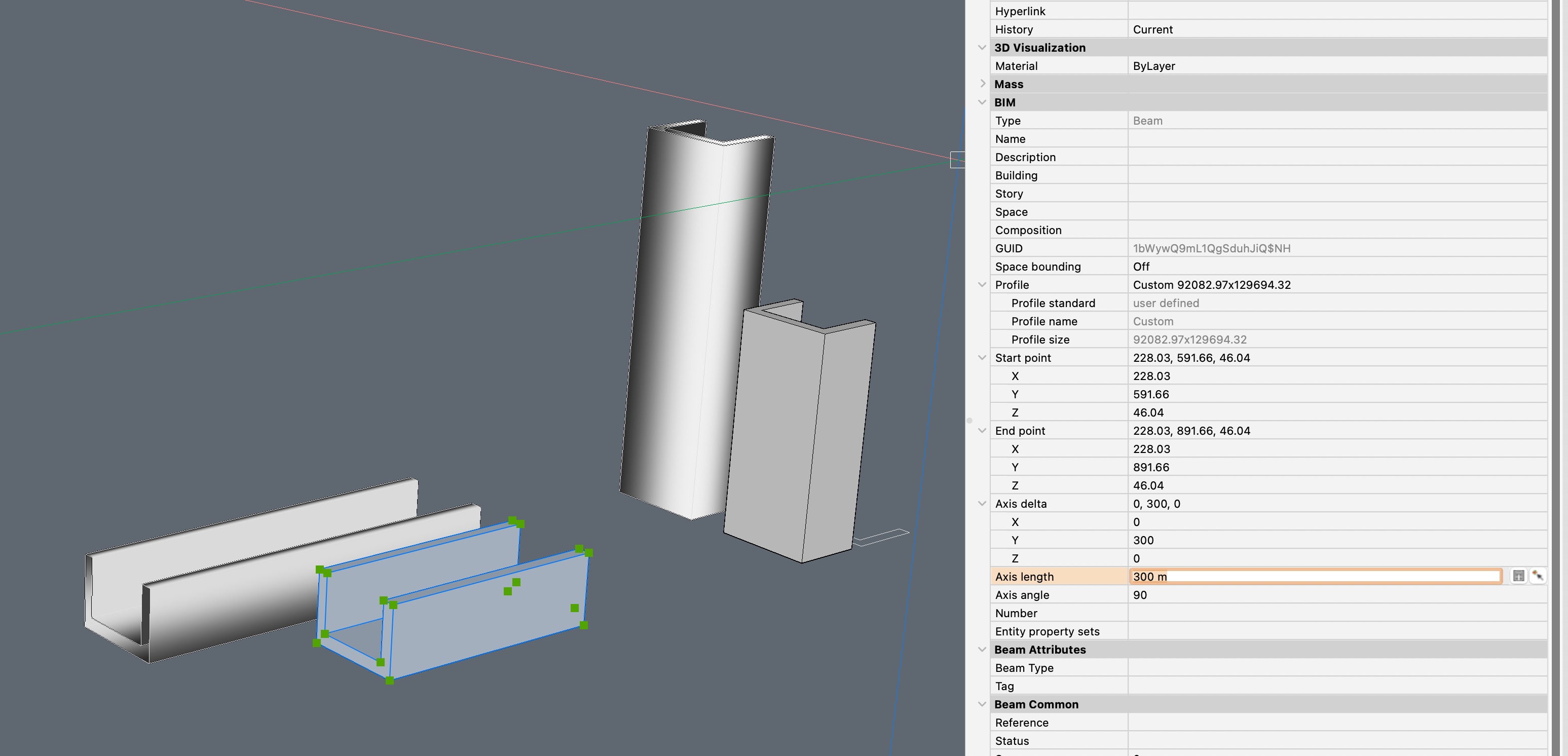 0
0 -
If you leave it as a Solid, without BIM, ….
Looks like Bricscad does not care about a Solid's Dimensions
(beside UCS Elevation top/bottom values which could work for vertical elements only)…. the only option I see is to extract one of the long Edges.
But I don't see options to automate this. Would be a manual process, like just noting each Polyline's Thickness on a piece of paper :)0 -
Yes, BricsCAD can't measure arbitrarily rotated parts. The AVC LAY plugin is used for this purpose: it lays out a solid with its main plane aligned with the XY axis and its longest side aligned with the X axis. Based on this same layout, the DDraw plugin can create drawings for each part and specify their dimensions. And the AVC SAW plugin can create a table with the overall dimensions of each part. So, extracting line lengths is no longer necessary.
0 -
Just a comment look at my April 11 post I tried using a UCS method and it drew a line the length equal to the thickness. Yes tested on 3D rotated pline with thickness. I would use the GCEN for the start position of the line used the 1st vertice of the pline for testing.
I think like Elvis @Manu25 has left the building.
0 -
Coincidence or not.
I just received a small job to quote with the exact same problem. (Studwork not shown) I'm only interested in the structural steel.
I've attached the drawing so maybe one of the above solutions may work. I would be keen to see if there is a solution.
PS I tried all the above but no winner.
thx Ian
0 -
You can get the thickness property from the objects, and add all of them up, is that what you want ?
This is just example code.
(defun c:PLLEN ( / len ss x obj)
(setq len 0.0)
(setq ss (ssget '(( 0 . "LWPOLYLINE"))))
(repeat (setq x (sslength ss))
(setq obj (vlax-ename->vla-object (ssname ss (setq x (- x 1)))))
(setq len (+ len (/ (vlax-get obj 'thickness) 1000.0)))
)
(alert (strcat "Total length is " (rtos len 2 2) "m"))
(princ)
)
(c:PLLEN)Explain more how you want say different totals displayed, a table maybe ?
0 -
thanks for the reply Alan
I was looking to convert them to solids. It’s not a big deal though, if I get the job I will just draw BIM profiles over them.
It would have been good to know if there was a way to convert them in bricscad.
0 -
I've attached the drawing so maybe one of the above solutions may work.
Uhm, your Polylines are even worse for BIM.
They are not closed.
I can close them in Properties but that will not help as these have no Fill. So I can't create Solids from them.
I looked closer to a Polyline Copy and set to 0.00 thickness. Like single Mesh Face that can't have a whole or an opening without being subdevided to have helper edges, this Polyline is drawn along the Profile with an Edge where start and end meet. Somehow Bricscad can't create a Face from it (!)I would have to create Boundary and extrude each manually ?
 0
0 -
If you don't want to convert polylines into solids and surfaces, there's another option. The AVC Zone command can convert all your polylines into flat contours of a specified thickness (by thickness, I mean the distance between parallel segments of a closed polyline, not the 3D thickness).
0 -
There is steel sections lisp out there, based on steel sections from around the world see attached may be useful. I have not played to much with them.
You may want to look at the shapes at moment they are on layer steel, could look at some properties of the pline and put them on correct layer, eg "100 sq tube"
Can you explain more what is the end goal why convert to solids ? Asked already about lengths.
A PS just set thickness to 0.0 then did a extrude of thickness value got a solid. Hollow tube.
0 -
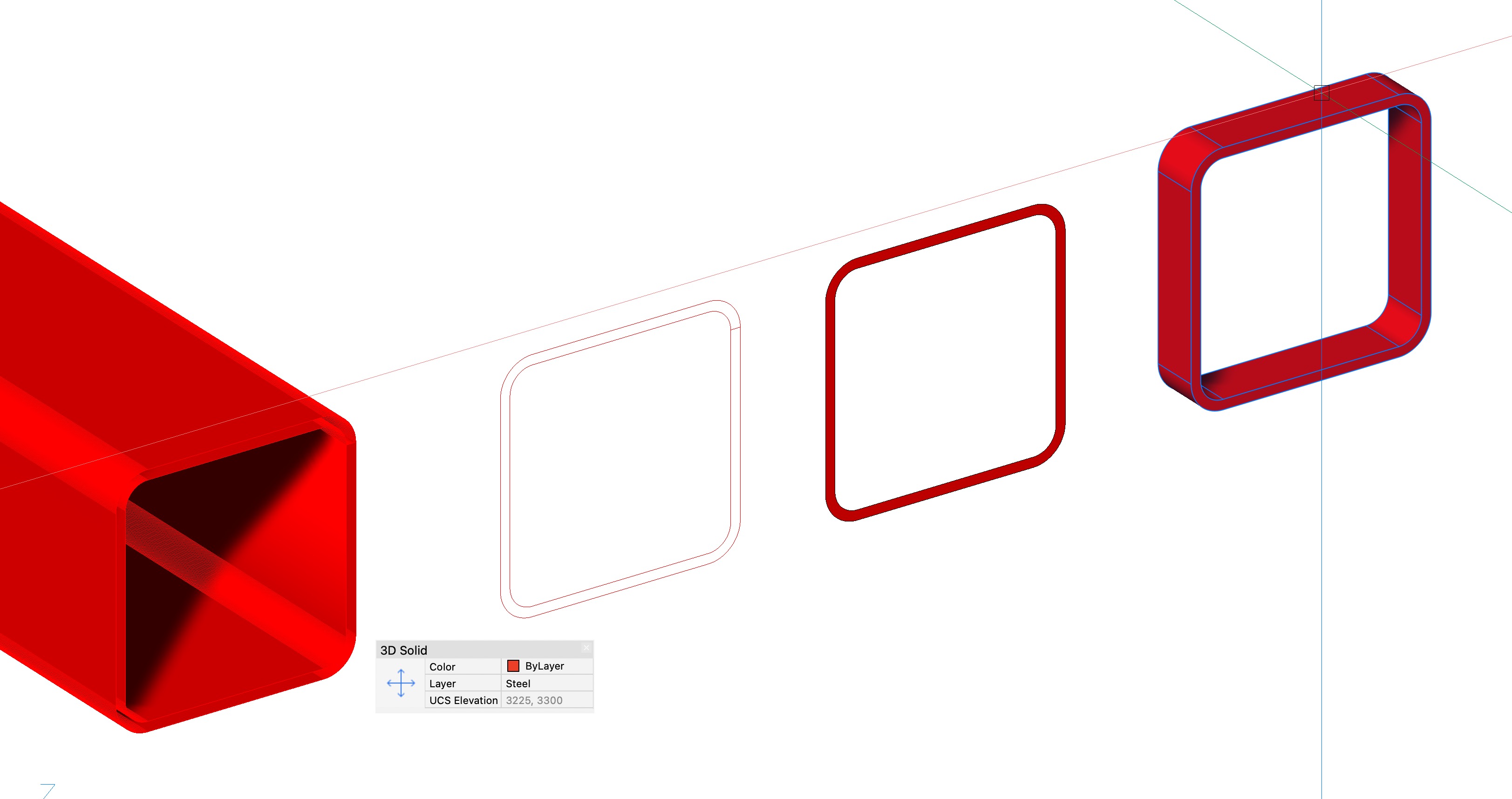
That's the winner Alan.
Set polyline thickness to zero and then extrude to the original thickness.
In my case I then BIMIFY to a beam and substitute the profile shown in the properties table to the nearest Aussie size available from Onesteel.
Could probably be done with a lisp routine as a single command I suppose.
Yes I have seen Wiseys shapes however I wrote my own 2D BHP shape routine 30 plus years ago. Its all Bricscad BIM and 3D these days.
cheers
1 -
Us Aussies have to stick together, I am near Newcastle NSW, where are you ? Can PM me etc. May have other useful stuff.
0