easy way to emboss/engrave text to a 3d surface

is there an easy way to do that? for now i do it in the following way:
1. write text
2. explode text
3. extrude text
4. place text in position
5. boolean operation (subtract) text from body/surface
there is often a problem in step2/3 already, because text polylines are often not closed and have to be reworked.
best regards, thorsten
Comments
-
Do you need a ortho-projection or something like the attached file??
Regards
Jochen
www.ant-ares.de0 -
No, the d=30 in the attached file.
i´m trying to model parts for 3d-printing, so text has to be embossed or engraved to become visible,
although your example looks interesting too...
in a video i saw this function in autodesk inventor working fine. just write a text, then push/pull it to desired height...
(not the "height" of the letters as in font-size, the "thickness fron e.g. z-plane when writin in x-y plane)regards, thorsten
0 -
Once on the face and exploded, I'd use the "boundary detection" selection mode to click-select the character glyphs and then do a subtraction extrude into the face of the solid. Boundary detection selection will tolerate "whiskers" where exploded bits of lines may intrude into the interior.
0 -
@Thorsten_Woell:
It may be worth creating components with BC_SUBTRACT functionality for each character you plan to use. But in that case I would look for a simplified font as the engraved text in the example increases the file size by a factor of 25.0 -
@Thorsten_Woell:
I have created a Lisp program to create 3D texts. It will take care of steps 2, 3 and 4 as listed in the OP. It is called BKG_3dText.0 -
Be aware though, that many types of fonts will explode into a large number of small lines. Depending on the amount of text, this can very quickly swell the file size.
Does anyone know if there such a thing as a duplex plotter font? This is a font that would, for example with the letter O, draw an inner and an outer octagon?
-Joe
0 -
@Roy Klein Gebbinck said:
@Thorsten_Woell:
I have created a Lisp program to create 3D texts. It will take care of steps 2, 3 and 4 as listed in the OP. It is called BKG_3dText.Roy,
I have been trying to convert some text objects (80 very short strings) to 3D using your LISP file. First problem I am having is the program will not allow me to select more than one text object. Is it possible to process more than one text object at a time? How? Second problem I am having is a huge file size. I only have a few SHX fonts that came with BricsCAD. They are all quite complex. Suggestions?0 -
Hi Jim, Roy,
for your information...
During the V18.2 life cycle, we introduced an enhancement for boundary detection that, as far as I see, failed to get a mention in the release notes,
perhaps because it sounded like a purely technical matter: in some cases boundary detection now produces nurbs instead of (spline-fit) polylines.So why would that be important?
Well, an exploded ttf text glyph consists of a collection of straight and spline-fit polylines.
Typically these spline-fit polylines have tons of vertices, which results in tons of small faces when extruding them, which results in heavy models.Now, if instead of selecting and extruding some joined polylines, boundary detection is used to obtain the desired text contour, and that boundary is extruded, the result will be a 'lean' 3d solid, consisting of just a couple of faces, instead of hundreds.
0 -
@Hans De Backer said:
Now, if instead of selecting and extruding some joined polylines, boundary detection is used to obtain the desired text contour, and that boundary is extruded, the result will be a 'lean' 3d solid, consisting of just a couple of faces, instead of hundreds.
That is pretty cool !
But so far my experience Extrudes from "Text"-shaped objects,
like shapes or profiles from "straight and spline-fit (arcs) polylines"
with "holes",
larger Slab objects (or rounded Walls) in my case,
was not so satisfying.Should I try to grab their Boundary and try to extrude them again
as Boundaries improved,
or could the poor screen resolution, that also will be used for "Mesh"
exports,
somehow corelate to the fact that I refuse to work in mm but use
m or at least cm ?0 -
Hi Michael,
not clear what you mean.
It would probably be more efficient if you attach some example to illustrate:
THIS is what I start from, and THAT is what I get and what I would like to see improved in the following way...0 -
Sorry, I didn't want to hijack other's Threads again.
I was thinking of these Situations.
(I set to Wireframe to make it Visible)
And already played with all kind of resolutions options in settings
(file?). Had a better result once ~~but was not able to reproduce
reliably and in a controlled way~~.
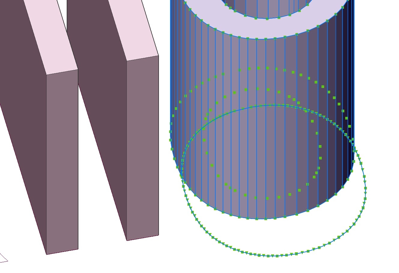
1. A course display of round Elements with larger Radii at all.
(Which will be meshed in the same resolution)
While Cylinders like my Columns behave Solid Modeling like "round".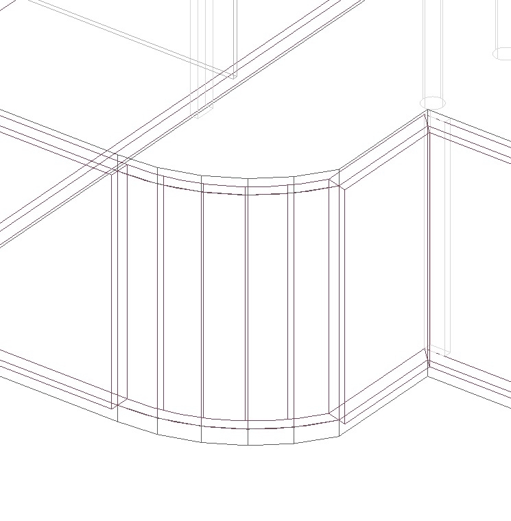
- That there is even a different curve deviation between the Round Wall
and the rounded piece of the Slab in the 2nd example.
Although both where created from the same (?) Arc, or at least should
have the same Radius.
And it looks irritating when trying to snap, when zoomed in, and the
cursor jumps to a point far from the curves "polygonal" representation,
which I think could be the real mathematical position of my curve
(but who knows)")
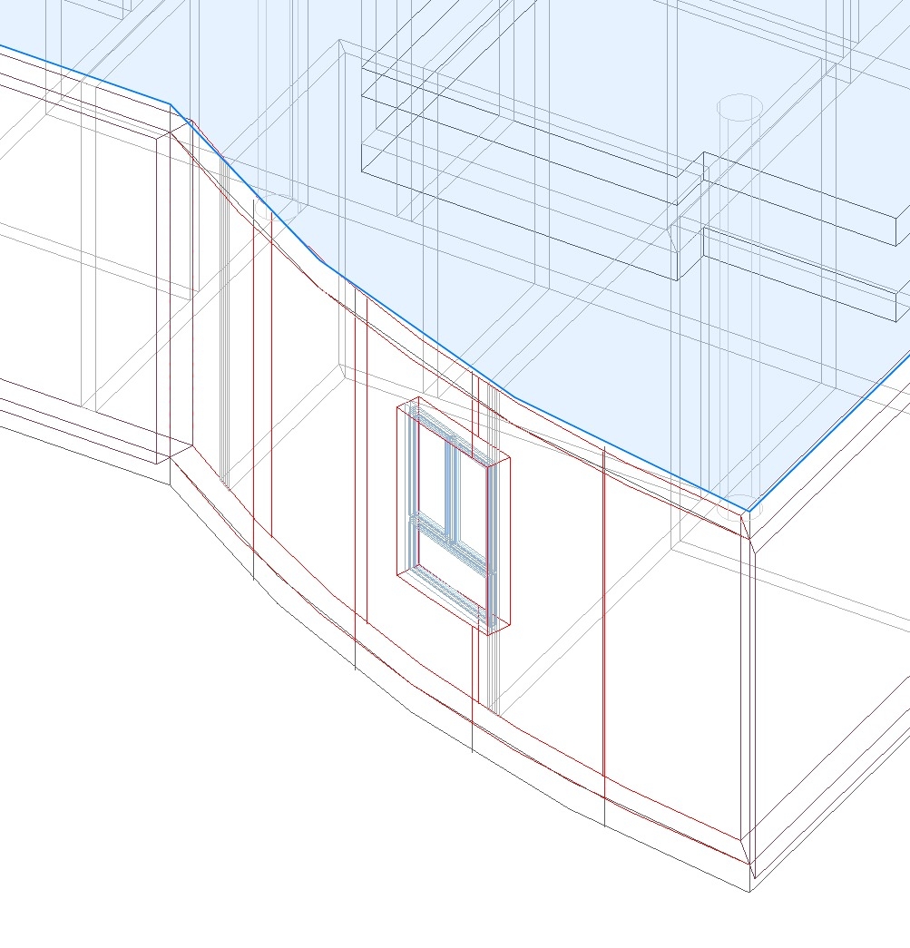
EDIT :
A shaded Screen Shot may be better understandable.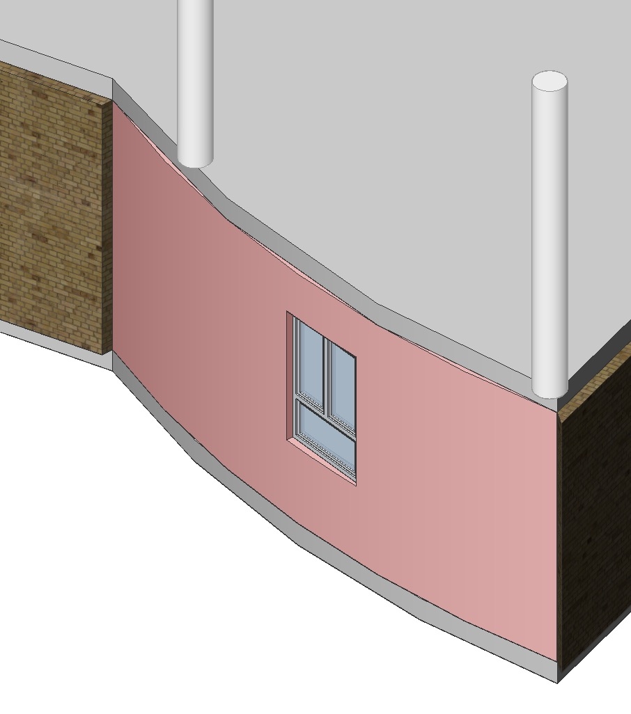 0
0 - That there is even a different curve deviation between the Round Wall
-
@Hans De Backer said:
Hi Jim, Roy,During the V18.2 life cycle, we introduced an enhancement for boundary detection that, as far as I see, failed to get a mention in the release notes,
perhaps because it sounded like a purely technical matter: in some cases boundary detection now produces nurbs instead of (spline-fit) polylines.
......Now, if instead of selecting and extruding some joined polylines, boundary detection is used to obtain the desired text contour, and that boundary is extruded, the result will be a 'lean' 3d solid, consisting of just a couple of faces, instead of hundreds.Hans,
I use V17.2.08. I also have V18.2.14 installed on my machine, but avoid using it. It loads extremely slowly and crashes a lot. However, I did bring up my drawing in V18 and tried to work with it. Not sure how I go about using boundary detection, but I checked my settings and see that boundary detection is checked.
I selected all my text objects (qty. 87, all in ARAGDTM font), invoked _TXTEXP (text explode) and then applied JOIN to the lines. I then tried to dmEXTRUDE the results but was unsuccessful. Roy said earlier that I have to use an SHX font instead of a True Type Font. But the only SHX fonts I could find on my computer were too ornate for a silkscreen layer. I found some SHX fonts online, but short of installing them all, I have no idea what they look like. Is there any way to view SHX fonts before they are installed?
Attached is a file with my circuit board layers, including the silkscreen. I moved the text from the silkscreen layer to a temporary layer to experiment with.
0 -
I tried Text too.
Looks like it is an Arial TTF.I used the Auto Boundary to Extrude.
For me it looks like the result is also polygonal,
same resolution as the Shape exploded from TTF.(18.2.23 Mac here)
 0
0 -
Hi Michael,
to investigate what exactly you are trying and why it gives an unsatisfactory result, the drawing is needed.
On a screenshot one cannot verify the properties of the entities that are used as input, nor can one investigate drawing settings, or the properties of the created entities and why they display segmented like that: is their definition segmented, or only their display, etc...0 -
Hi Jim,
as I wrote in my previous post, the procedure I described is meant for TTF (TrueType font) text, not SHX text.
What Roy wrote about preferring SHX text is **specific ** for the utility Roy developed.
When extruding exploded SHX text you will not obtain 3d solids but zero-thickness surfaces instead, which is not what you are after.To try what I described, take a TTF text, use TXTEXP to explode it into polylines, no need to join them, hover the cursor inside a text glyph contour so the glyph boundary gets selected and use the Extrude tool from the 'Model' tab of the Quad: this should produce the desired 3d solid.
To verify if your boundary detection is On, open the Settings dialog and enter 'SELECTIONMODES' in the search field: SelectionModes consists of 3 check boxes ('flags'). Make sure the 'Select detected boundaries' checkbox is checked.
0 -
Hi Hans,
I extracted parts of those elements to a new file.
(BTW INSUNITS were already mm)
Hope that helps, as it looks same as the original file.0 -
Hi Michael,
the definition of your curved wall is smooth, e.g. when generating a plan section, a smooth curve will be produced for that wall.
What is not smooth is the tesselation that is used to display the wall.
You could increase facetres to the maximum value of 10, but for this kind of curved faces with a small curvature, the maximum facetres value may still be considered 'not smooth enough'.Instead of using the one-size-fits-all facetres setting, you better tweak the Surface Tolerance, the related variable has the beautiful name 'spaSurfaceTol'...
Its default value is -1, meaning that the system will try to find an optimal value for the model you're working on.
For your model, this automatically chosen value seems to be about 15 degrees, which is fine for the cylindrical columns, but not for that wall.
In models containing solids with small curvatures, you may want to set it to 1 degree.Only modify this setting when needed: it comes at a cost, much more triangles will be generated and needed to be rendered on your screen to display curved solids, which means: slower regen and slower redraw.
Concerning the vertical lines you see in this wall when in wireframe mode: these are not divisor lines between wall segments, they are 'isolines', meant to make the image easier to understand when displaying geometry with curved faces. The number of isolines is controlled by the ISOLINES setting.
Finally, concerning the text you tried to extrude: if you don't join the polylines before extruding the boundary you will get a smooth result.
Kind regards
Hans0 -
@Hans De Backer:
Thanks for the info regarding the improved boundary detection. It works well. The _Region command seems to use the same optimization, and for Jim's case creating regions as an intermediate step seems more practical than clicking inside the contours of more than 300 letters (although you will have to _Subtract island regions).
Strangely enough extruding surfaces from the outlines of letters shows that they are not optimized in the same way. Perhaps an oversight?EDIT:
Oops, there has been an oversight on my part instead. The 'optimized' region is created in V19 Beta, not in V18. And in V19 Beta surfaces are optimized as well. Sad news for Jim then: he will have to click those points (or wait for the official V19 Release).0 -
Thanks a lot Hans !
That explains a lot. I will go through all.0 -
@Hans De Backer said:
Hi Michael,Finally, concerning the text you tried to extrude: if you don't join the polylines before extruding the boundary you will get a smooth result.
Kind regards
HansI don't get that to work.
I didn't join anything.If I explode my Text
(doesn't work with my "3D ?" Explode, but Explode from Quad)
I'll get closed Polylines.
Even if I Explode these too, Boundary will work but I'll get a
polygonal Solid after extrusion again ?Does it maybe depend on a specific TTF Font or just that I am using
the Mac Version ?0 -
It could be that this improvement did not yet make it into a Mac release.
Sorry but at present I don't have the time to check this...0 -
No problem,
thought about something like this.
Will try on Windows at one point.0 -
Regarding Michael's issue also see:
https://forum.bricsys.com/discussion/33865/extruding-smooth-2d-object-to-3d-increase-polygon-count
Contrary to what Michael says in that thread increasing the FACETRES does work for the file he posted here.0 -
I did not say that FACETRES does not work,
I just said that I was not able to reproduce my former Test Settings.
That includes missing enthusiasm, time and other diversions0 -
@Michael Mayer:
I am referring to this remark:Not sure if is the right setting but FACETRES (activated by default ?) and setting the number from 0.1 to 0.5 seems to make circles look better. (Unfortunately not my rounded Walls)
Changing the FACETRES does affect the display of the rounded walls in the file you posted here.
0 -
Yes, but someone already mentioned there that I can blow the number
up to 10, which I was first afraid of using, because it starts with a low 0.1,
I found a reasonable setting at that time but forgot again.But indeed, 10 does still not work ....
you better tweak the Surface Tolerance, the related variable has the beautiful name 'spaSurfaceTol'... Its default value is -1
That works well with 1.0
(until Bricscad crashed when switching between view modes and
zooming in)0 -
@Hans De Backer said:
It could be that this improvement did not yet make it into a Mac release.
Sorry but at present I don't have the time to check this...I tried in Windows with the existing file and got only the same result
as in macOS.
It only worked after I created a new Text Object in Windows,
Exploded in Windows,
then the Extrude was round instead of faceted.Funny thing is, if I create the Text in Windows and explode in Windows,
Extruding in macOS is smooth too.
When I create the Text in Windows but Explode on Mac,
Extrude won't be smooth.So I think, Mac doesn't "Explode" as nice as Windows.
Although the exploded results look identical from both OSs.
2D Polyslines.0 -
@Michael Mayer said:
But indeed, 10 does still not work ....Are you using the _Regen command after changing the FACETRES setting? If you still do not see an effect after regenerating, try saving two versions of the dwg: one with a very low FACETRES setting, the other with a very high setting, and check the difference in Shape. Some of the other settings Hans has mentioned are not stored in the dwg and can have an effect as well. In Shape these will have default values.
0 -
I switched files but tnow tried regen too.
FACETRES 10 looks noticably better but it still doesn't look round
and when zoomed in Wireframe, Lines between
rounded Walls/Window Cuts and butted linear Walls
still don't match.With spaSurfaceTol 1 it looks very good.
And when I 3DCONVERT or DAE Export :
small Columns vs larger rounded Parts from flat Arcs,
both types of Mesh Resolutions look pretty decent.(BTW, would be nice if DAE Export had an option to define the Up-Axis
for Coordinates - because most 3D Apps think that Y instead of Z should be
the Up-Axis)0


