how to create a new pattern or where to get additional patterns
I an designing landscape for a road. My segment starts where another designer segment ends. I want that graphically our drawings will look identical/continuous. He used a pattern that he created in AutoCAD (simple square blocks pattern with staggered verticals). Nothing like that exist in bricscad (we have only rectangular blocks pattern) so I want to make a custom pattern but have no idea how. Sow some samples of .pat files on the net but no guidelines on how to write them. I assume each number there defines coordinates of dashes but what each of them means, their direction and location etc. are not known.
I am looking for guidelines of creating patterns &/or .pat files to download. Any help will be welcome.
Comments
-
Thank you Garry
Yes, this is exactly the sample I have see earlier and my question related to it. Have you used it? I assume that each line of numbers represents one dash. My question related to each one of the numbers in one raw.
1. I assume that first number in each line represents its angle but does 00, means left to right or right to left and does 90, means from bottom up or from top down?
2. Second number I assume are start coordinates of a das and I assume 0,1 means x-0 and y=1. is it so?
3. a sequence of 3 numbers like 1, 2, 3, comes next what does each one of them means. I assume one of them represents distance to next and I also assume its the 3rd one in this sequence> right? wrong?
4. 4. the last number with the minus in front - what is it?0 -
Not sure, but if the designer e-transmits the file to a zipped folder, he should be able to include the hatch pattern for you. Saving you the need to make a new one.
Anybody, is this correct ?
0 -
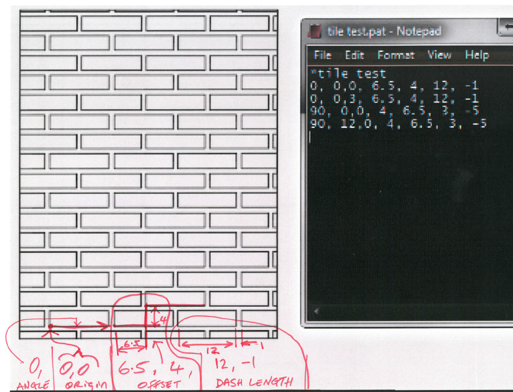
I'll try explain the first line of the example:
0, 0,0, 6.5, 4, 12, -1Yes, the first number is the angle that the dash will be drawn. 0 is horizontal left to right. 90 is vertical bottom to top.
Yes, the next two numbers are the start of the dash x , y coordinates.
The next 2 numbers are the offsets of the dashes. So the first dash will be repeatedly offset in x by 6.5 and in y by 4.
The last two numbers is the length of the dash. Negative numbers will give you a space. So the first dash will be 12 long with a 1 unit space. You can have as many numbers here as necessary up to a maximum of 80 characters.
0 -
@DFLY said:
Not sure, but if the designer e-transmits the file to a zipped folder, he should be able to include the hatch pattern for you. Saving you the need to make a new one.Anybody, is this correct ?
Thank you DFLY, I think you should be correct as there is an option "inherit properties" so theoretically I should be able to do it however in my trials it never worked - guess something was missing.
0 -
@Garry O'Mahony said:
I'll try explain the first line of the example:
0, 0,0, 6.5, 4, 12, -1Yes, the first number is the angle that the dash will be drawn. 0 is horizontal left to right. 90 is vertical bottom to top.
Yes, the next two numbers are the start of the dash x , y coordinates.
The next 2 numbers are the offsets of the dashes. So the first dash will be repeatedly offset in x by 6.5 and in y by 4.
The last two numbers is the length of the dash. Negative numbers will give you a space. So the first dash will be 12 long with a 1 unit space. You can have as many numbers here as necessary up to a maximum of 80 characters.
Thank you Garry, makes sense. Will try to make my own pattern later. Keeping my fingers crossed
0 -
I am quite regularly making small changes to dwg files exported from ArchiCAD, so none of the used hatch patterns is available in BricsCAD.
If I would have to recreate all these patterns manually, I would go insane... luckily, this is not needed:
As you mentioned, ADDSELECTED will not work on such hatches, but you can copy the hatch and then use the ASsociate option of -HATCHEDIT to assign it to a new boundary.0

