Constant slope of curve/path like in Blender?
Hi all community,
how should I approach modeling constant slope pathway in BricsCAD?
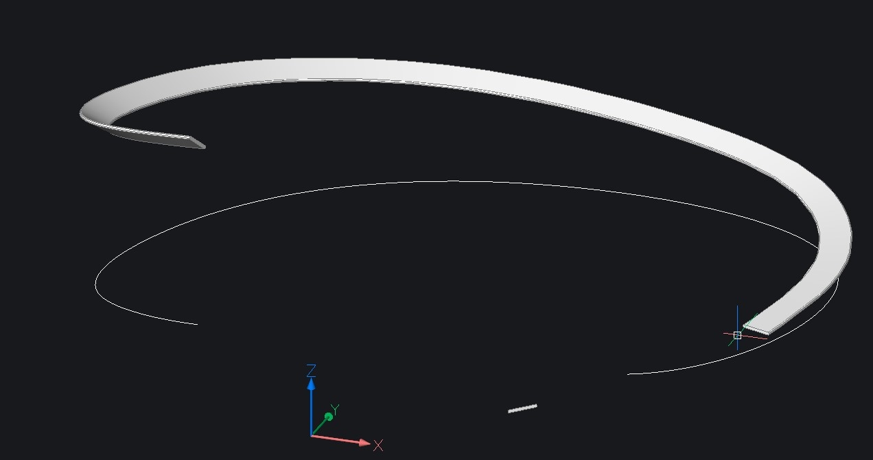
I am talking about watchtower with path to top. Something like in the picture...
I need to construct the curve that will represent path direction in 3D space and then use it as path to model wood path, railings with columns, bearing steel construction under path etc.
This curve needs to have same slope on its whole lenght. I know start elevation in Z direction and ending Z elevation. Between start and end the curve is randomly traced between bearing columns in TOP plan.
I tried to use spline and I was able to elevate control point in properties. But I need to distribute other vertices on the curve in Z direction. Can this be done somehow?
OR
simpler solution would be to "set slope" on spline and then only edit shape in TOP plan - this would be awesome! (that is the way a make it in Blender)
I work a lot in Blender, which is great 3D polygonal software. Problem is, that when I make concept project and visualization, it is always needed to transform model to CAD applications (for making drawings, annotating, statics caculations etc.) It is always very time consuming for me and my colleagues.
Therefore I am considering to switch my workflow - model in CAD and make visualizations in Blender by exporting from CAD. I know that Brics can export fbx. which is great. But i am struggling with this type modelling I wrote. We do this kind of structures almost all the time.
Thanks for ideas and possible solutions in BricsCAD (I am not familiar with it much).
Comments
-
Another way for my worflow would be to model pathway in Blender (like I do now) and import through .dae to Brics
Can I somehow "extract" curve from imported mesh in BricsCAD?
0 -
"Can I somehow "extract" curve from imported mesh in BricsCAD?"
What do you mean with extract? What should the output look like?
Is this perhaps a flatten operation for cutting and sawing?0 -
@Hans Lammerts said:
What do you mean with extract? What should the output look like?
Is this perhaps a flatten operation for cutting and sawing?I need some curve as output (polyline, spline,....) which can be used to copy objects and sweep profiles along this curve in 3D.
When I import Blender to Brics, which i tried, meshes are imported. After explode they are 3D polygons. I would need to make polyline or spline from this mesh. Only way I can think is start a spline and click through thousands of points manually, which is not possible in the time I ussually have...Anyway, better way should be to model this slope/curve path in Bricscad :-D if U have any idea how?
This was my first intention, to model everything in BricsCAD, but I have problems with those curvy pathways...0 -
To my knowledge there is no built-in solution. But it should be possible to write a (Lisp) program that creates a 3D spline or 3D polyline based on a 2D spline and some parameters.
0 -
@Roy Klein Gebbinck said:
To my knowledge there is no built-in solution. But it should be possible to write a (Lisp) program that creates a 3D spline or 3D polyline based on a 2D spline and some parameters.Hmm, not glad to hear that...So I will try to find another solution, because I do not really know what Lisp is and how to write a program at all :-D
But I tried simple thing today....made spline, cut it intyo same lenght segments and this gave me points, which can be then elevated in Z coordinates a put new spline directly through them.Which is kind of the same as my old method. To import from Blender and clicking new spline through points on the imported mesh.
0 -
From my limited experiments, and limited experience with splines, I conclude that the slope of a spline created in that manner is not really constant. But you may be able to come close if you use many points.
Below and attached is a simple Lisp program that may help:
General instructions regarding the use of Lisp programs:
http://www.b-k-g.nl/loading-lisp-programs.htmlAfter loading the code type
SlopeSplineto start the command.(defun c:SlopeSpline ( / cnt doc enm hgt i len new obj pt ptLst) (setq doc (vla-get-activedocument (vlax-get-acad-object))) (vla-endundomark doc) (vla-startundomark doc) (if (and (or (= 1 (getvar 'worlducs)) (prompt "\nError: WCS required ") ) (setq enm (car (entsel))) (setq obj (vlax-ename->vla-object enm)) (= "AcDbSpline" (vla-get-objectname obj)) (or (equal '(0.0 0.0 1.0) (vle-entget 210 enm) 1e-8) (prompt "\nError: spline not parallel to XY plane ") ) (setq hgt (getdist "\nTotal height: ")) (setq cnt (getint "\nNumber of fitpoints: ")) ) (progn (setq len (vle-curve-getperimeter obj)) ; Hor. length. (setq i cnt) (repeat cnt (setq pt (cond ((vlax-curve-getpointatdist obj (* i (/ len cnt)))) ((vlax-curve-getendpoint obj)) ; Just in case. ) ) (setq ptLst (cons (list (car pt) (cadr pt) (* i (/ hgt cnt))) ptLst)) (setq i (1- i)) ) (setq new (vla-addspline (vla-get-modelspace doc) (apply 'append ptLst) '(0.0 0.0 0.0) '(0.0 0.0 0.0) ) ) ) ) (vla-endundomark doc) (princ) )0 -
Hello Roy,
good to see you are still sharing your expertise here (and sad to see the lack of response), thanks a lot for the code, as so often.
However, I think that this example points to the current limits of modeling in BricsCAD/dwg:
While blender has a path object that allows for control of the its lateral slope, dwg lacks a counterpart, which leads to more or less unwanted warping of the profile around the path when sweeping - imagine the geometry in the first attached screenshot serving as the intended pedestrian ramp...
To produce the geometry asked for in the OP inside BricsCAD, you IMO have no option but to create a patharray first, then explode this and use profiles and path as input to the loft command (as in the second screenshot).
And while you can link a profile to the path in blender, each small adjustment needed to the path will have you start over again in BricsCAD.
So I guess for the moment my answer to the OP would be to better stick to blender for conceptual modeling, and switch to BricsCAD once the final shape has been established.
0 -


Thank You for Your time guys.
@Roy Klein Gebbinck Your Lisp indeed does elevate curve evenly, which is really handy. But then comes the second problem like @Knut Hohenberg wrote. That profile rotation along spline is problem for this kind of sweeping. Can this be somehow overcome?
Blender and some other apps have possibility to maintain Z axes
This cannot be specified in sweep command?...or I could not find it? :-)A started to hate Vectroworks (too many bugs and perfomancea issues) so I will almost surely switch to BricsCAD which is great in so many ways. Only downside are some of these limitations.
But what You think, this should to possible to implement nicely right? This would part solution, but EVEN better would be to implement same technigue as with new road feature presented in this video from 43:01 time...only to have this feature in 3D modeling without terrain and possible to change heights of curve or slope between control points...Then adjust curve shape in x/y like in the video.Anyway, I will stick my workflow now and try Blender to Bricscad workflow soon.
Thanks guys
0 -
Knut's suggestion to use the _Loft command is probably the way to go here.
Below and attached is a new version of SlopeSpline. I have added a feature (offset) and fixed an error.
(defun c:SlopeSpline ( / cnt doc enm hgt i off obj pt ptLst segHgt segLen) (setq doc (vla-get-activedocument (vlax-get-acad-object))) (vla-endundomark doc) (vla-startundomark doc) (if (and (setq enm (car (entsel))) (setq obj (vlax-ename->vla-object enm)) (= "AcDbSpline" (vla-get-objectname obj)) (or (equal '(0.0 0.0 1.0) (vle-entget 210 enm) 1e-8) (prompt "\nError: spline not parallel to XY plane ") ) (setq hgt (getdist "\nTotal height: ")) (setq off (getdist "\nOffset distance (can be negative): ")) (setq cnt (getint "\nNumber of fitpoints: ")) (or (< 1 cnt) (prompt "\nError: at least 2 fitpoints required ") ) ) (progn (setq i (1- cnt)) (setq segHgt (/ hgt i)) (setq segLen (/ (vle-curve-getperimeter obj) i)) (repeat cnt (setq pt (vlax-curve-getpointatdist obj (* i segLen))) (if (not (zerop off)) (setq pt (polar pt (- (angle '(0.0 0.0 0.0) (vlax-curve-getfirstderiv obj (vlax-curve-getparamatpoint obj pt))) (/ pi 2.0) ) off ) ) ) (setq ptLst (cons (list (car pt) (cadr pt) (* i segHgt)) ptLst)) (setq i (1- i)) ) (vla-addspline (vla-get-modelspace doc) (apply 'append ptLst) '(0.0 0.0 0.0) '(0.0 0.0 0.0) ) ) ) (vla-endundomark doc) (princ) )0 -
Man, You are awesome! It works well. This is acceptable workflow. If I maintain my flattened curve I can easily recreate whole path in few steps! Super :-)
Sorry for maybe dumb question (not familiar with Bricscad much, yet)....lofting makes segmented curves as seen screenshot. Where can I set to follow curves closely? I tried setting after loft, but did not do anything on any option I chose.Thank You for helping me out. I see that BricsCAD is awesome and its community also :-)
0 -
The _Loft command has a _Guides option. But what you are seeing is related to the FACETRES (facet resolution) setting, the actual solid is not segmented.
0 -
Hi all,
Maybe the alignment tools in BricsCAD V20 can also be used. You start by defining the horizontal alignment. This is a 2D curve which is needed to precisely position linear objects in a horizontal direction. It is defined by the Points of Intersection (PI). Next, you can define a vertical alignment to precisely define linear object in vertical sense. Here you can draw a line with a constant slope. The result is a 3D alignment, which is a 3D polygonal curve defined by the horizontal and vertical alignment.
https://help.bricsys.com/hc/en-us/articles/360008104159#procedure-creating-an-alignment
0 -
@Tiemen said:
Hi all,Maybe the alignment tools in BricsCAD V20 can also be used. You start by defining the horizontal alignment. This is a 2D curve which is needed to precisely position linear objects in a horizontal direction. It is defined by the Points of Intersection (PI). Next, you can define a vertical alignment to precisely define linear object in vertical sense. Here you can draw a line with a constant slope. The result is a 3D alignment, which is a 3D polygonal curve defined by the horizontal and vertical alignment.
https://help.bricsys.com/hc/en-us/articles/360008104159#procedure-creating-an-alignment
Gonna try it this approach too. Thanks for the tip :-)
0
