BIM Generated Drawing Layers

Hello:
I have made up a model of my project and now I need to make some drawings but I cannot wrap my mind around how the software is setting layers. My section planes have been set so that all generated layers have a prefix, for example HiddenLines_EntityLayer or Boundary_EntityLayer. Then using the composition or layer if no composition is assigned the software generates layer names, the appropriate prefix being chosen in the background based upon where the entity is in relation to the section plane:
- If source entity has no composition: [Prefix]_[Source entity layer]
- If entity has a composition: [Prefix]_[Composition ply name]
In my model nothing is drawn on layer 0 and almost every entity has a composition (typically I use a composition only if I need to show the plies of an entity in my drawing, or if I need to define a specific hatch). When I generate my drawing views my generated section places some (well a lot) of entities onto layer 0, the section block itself is then placed onto layer 0 as well, some annotations are then placed onto the current layer (like steel profile names for instance). Now I use Layer Freeze with VPFreeze to freeze individual layers in the generated view so that I can see only specific things, the trouble here is that both the selected entity and the section are drawn on layer 0, so as soon as I click the entire section disappears from the viewport. I check my model and regenerate and I cannot figure out how or why some entities are being tossed onto layer 0 in the generated section.
From all of this my questions:
- How do I set which layer the generated section block is placed onto, for discussion I want the software to place it onto a layer called BIM_DrawingView
- Why are some entities showing on layer 0 in the generated section view when the section plane definition and source entity do not reference layer 0 nor is this the current layer set in the target drawing for the section block output
- How do I set the layer upon which annotations are placed (some of these are blocks defined in a drawing file and referenced when the section is generated)
Really the software is pretty slick, the modelling is easy and it makes nice looking drawings but I have a lot of trouble sorting out where or why certain layers are created. One thing that I did in my setup was to add a prefix to all of my Materials and Compositions, this allows me to quickly differentiate between the generated layers and script via a lisp to quickly change the colours of layers with a specific prefix to a certain colour and linetype. This definitely made things easier for me but I am still seeing issue with the above...
Comments
-
Hello Scott,
Thanks for the feedback! Based on your description, I also cannot figure out why some entities are being tossed onto layer 0 in the generated section. Your described approach seems to be correct, and it is expected that the generated lines follow the rules of the section plane settings. It would be helpful to understand which entities exactly end up on layer 0, but let me already explain briefly the logic of the generated section line layers.
Firstly, the layer name of the entities being sectioned are determined by the section plane settings (which can be found in drawing explorer). By default, boundary lines are put on a layer "Boundary_EntityLayer", fill lines are put on a layer "Fill_EntityLayer", etc. The defaults are stored in the following file "Bim/Sections/_SectionSettings.dwg", which can be found in your support folder (run SUPPORTFOLDER command in BC to open). As a result, a layer will be created for every combination of intersection line and material name:
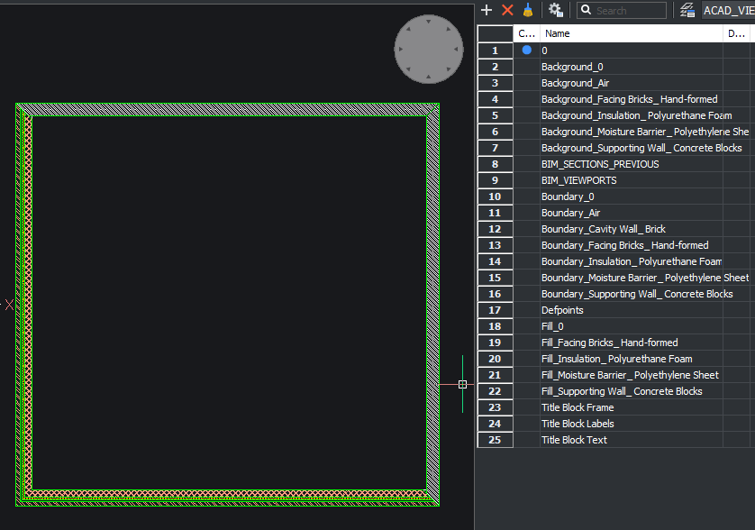
Secondly, in the composition editor (BLCOMPOSITIONS), it is possible to override the layer by assigning the material to a dedicated layer (in the material editor > Appearance tab > Section tab > Layer field). This will override the layer of the sectioned entity.
The layers are retrieved in the following way: (1) if the layer already exists in the section result drawing this layer will be re-used, (2) if the layer exists in the "Bim/Sections/_SectionSettings.dwg" template drawing it will be copied from there, and (3) if the layer exists in the model drawing it will be copied from there. If the layer does not exists in any of these three cases, it will be created from scratch with default layer settings.
For now, the section result block will always be created on layer 0. It is also not possible to configure the layer upon which annotations are placed, but you can expect some big improvements for placing tags and other annotations in our upcoming release.
Please check these suggestions if everything is set-up correctly. If that does not solve the problem, it would be helpful to file a support request and include your drawing, so we can have a look how it can be fixed.
Best regards,
Tiemen0 -
Hi Scott,
What happened to me is that I set a multi-storey building per floor. I modelled each floor in a separate file, adding composition, spatial location....and xrefed all floors in another dwg.
When I generated sections a block wall layer became a reinforced concrete layer, changing representation. Something bizarre, is that BRX 2d swing representation became an independent layer, not like Boundary_BRX 2D Swing and the swing polyline went to layer 0.
What I did to sort that out was to bind-insert that xref-floor and work in floors inside the big file. When doing that, the penetration of material and layer changing/messing stopped and representation was ok, but couldn't work as floors as independent xrefs, but independent blocks.
I don't know how you structure your building storeys, but try something in that sense. Please, let me know what happened later.
Regards,
Maurilio0
