Design approach pile component for piling box

Dear all,
I am trying to resemble the Revit example for a piling box as below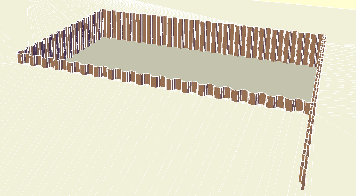
I have taken a U-profile and parametrized from a vendor catalogue and added a design table as follows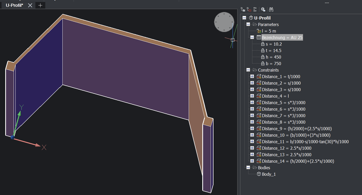
My nooby idea is to draw a rectangle polyline and project the component along and then to adjust either U-profil component and/or rectangle size in order to arrive at proper corner overlaps. 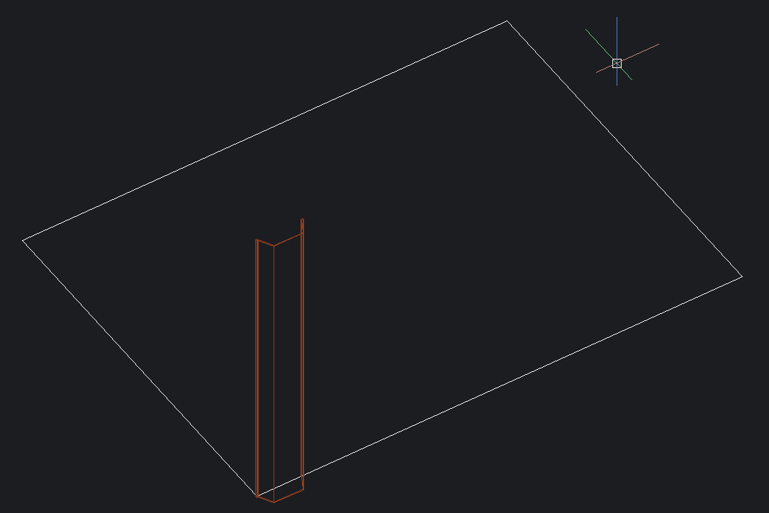
What would be a flexible approach to this matter?
Kind regards
Sebastian
Comments
-
My first approach is to insert the created component, then insert another attache them according to shape as below
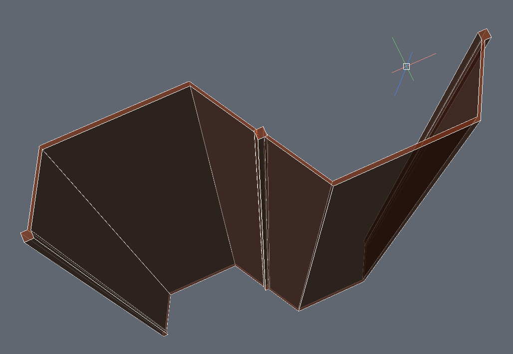
And projecting the solids as ARRAYRECT:

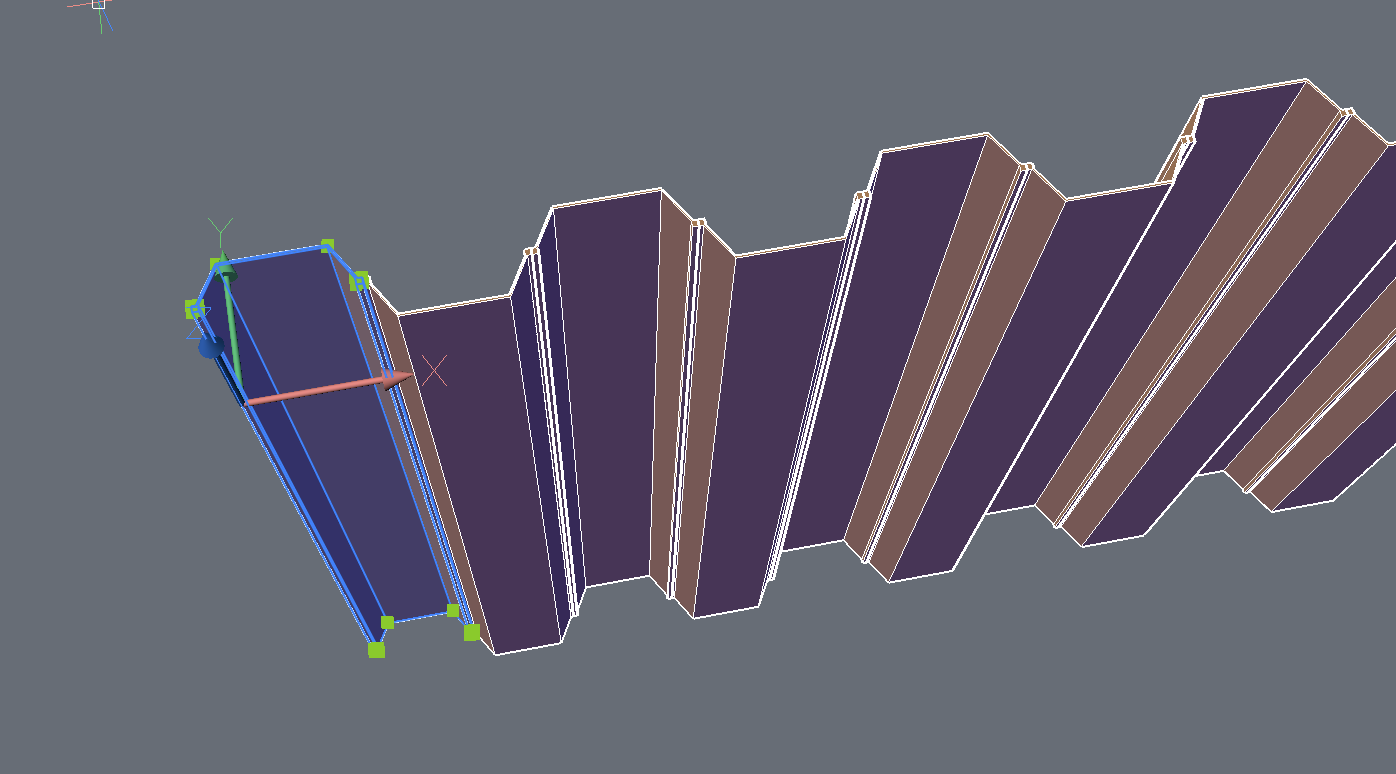
Then I add a single component to finish the corner. I am not able any longer to edit properties (e.g. length) for a single pile. Better would be to preserve the ability to edit the length for every single item.
0 -
Why not creating a Block for one part and do an Array.
Is it that Revit offers you to automatically fill them around any Polygon ?0 -
@Michael Mayer
In Revit it seems to be called a line-based row ("Reihe Linienbasiert") which I would interprete as an array. One is able to scale dynamically, so it could be an _arraypath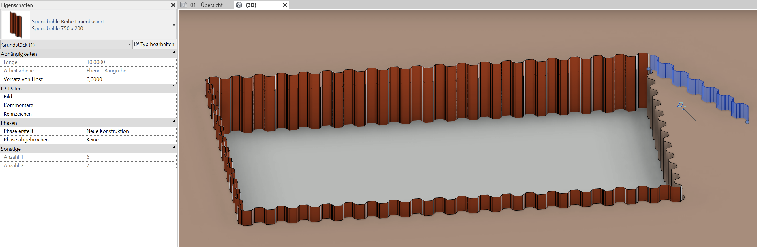
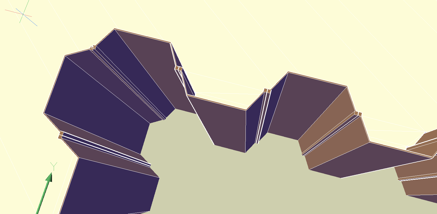
The detail looks as follows. I interprete one pile as a component. They seem to be stitche to a group.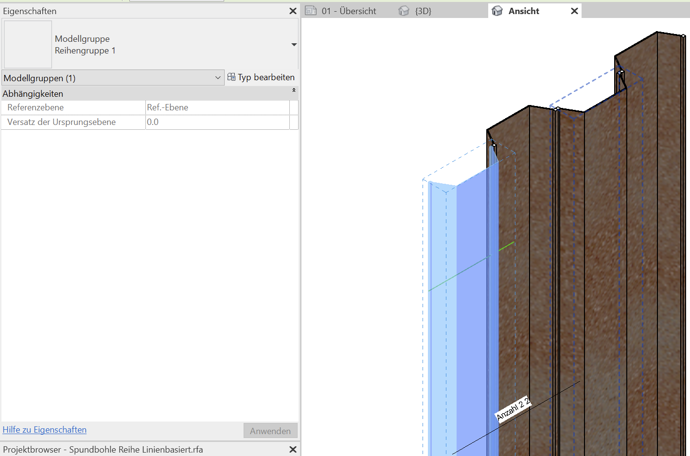
Seems like I need to learn about _arraypath and how to generate components to align properly0
