Linux BricsCAD and InPower 0.97.45 For Power Factor Correction Sizing

Power Factor Correction Example
Using BricsCAD InPower Ver. 0.97.45
December 2021
Using BricsCAD InPower Ver. 0.97.45
December 2021
Large industrial motor loads can cause the electrical power system power factor to drop to 78% or even lower. This low power factor causes unnecessary current flow and power I^2R losses in the electrical power system equipment. Electric Utility companies will typically charge a monthly fee for excessively low power factor. Power factor is defined and the cosine of the angle between the real power (P) and the reactive power (Q).
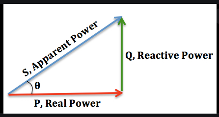
Figure 1.
On the complex plane, inductive motor reactive power (Qm) can be thought of as positive, where capacitive reactive power (Qc) is negative. The vector sum of the motor Qm and the capacitor Qc reduces the angle to increase the power factor. The real part of the motor power (P) stays the same.
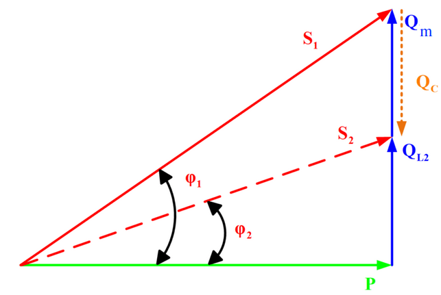
Figure 2.
BricsCAD InPower is used to size just the right amount of capacitor to change the power factor from 0.75 to 0.95. Or 95% power factor.
A large motor lumped load for a waste water plant is shown below at Bus-17 in figure 3. The BricsCAD InPower power flow for the facility shows -2.0 MWatts for the real motor power and -1.6 MVars for the reactive part. The sign of the power is relative to the generator. We will need to add positive capacitive MVars to adjust the power factor closer to 1.0. The cable feeding Bus-17 shows 3.157KA of current at 78% power factor. Cos(ATan(1.6/2.0))=0.78 or 78%
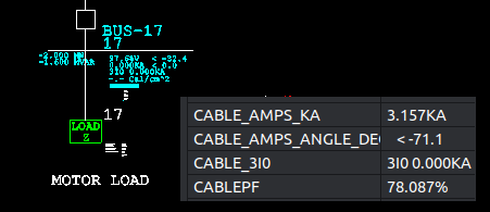
Figure 3.
Capacitor banks come in discrete sizes such as 200KVAR shown in Figure 4. We will incrementally add 200 KVAR until we get to 95% power factor. We will start by adding 50% of the -1.6MVar motor inductive power. 50% of the 1.6MVar = 800 Kvar capacitor bank.
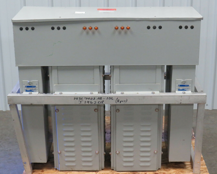
Figure 4.
You can see from figure 5 the new BricsCAD InPower power flow shows -2.0MWatts and -0.800 Mvar real and reactive power for the plant. The capacitor reduced the reactive power to (-1.6 + 0.8) to -0.8 MVars and a total cable current of 2.6KA. The power factor is increased to 92.8%. Not quite 95% but close.
We will add another 200 KVAR capacitor bank for a total of 1000 KVar and run the BricsCAD InPower again.
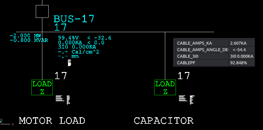
Figure 5.
Figure 6 shows -2.0 MWatts and -0.600 MVar inductive load for Bus-17 and a significant cable current reduction of 641 amps. The power factor has been adjusted by the 1000 KVar capacitor bank to 95% using BricsCad InPower. This reduction in power factor saves I^2R losses and energy. A reduction in the utility power bill is a possible payout for the efficient installed cost.
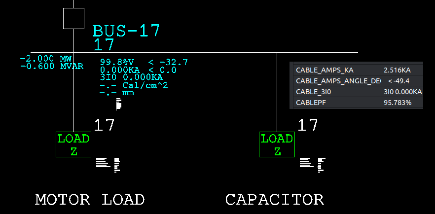
Figure 6.
The exact calculation is,
The new needed power factor is 95% or the angle is ACos(0.95) = 18.19 Degrees . The new angle after addition of the needed capacitor banks is 18.19 degrees.
The exact calculation is as follows,
P=2.0
Qold=1.6
Calculate the new needed magnitude of the complex power.
S = P / Cos(Angle) = 2.0/0.95 = 2.1053 MVA
Calculate the new angle
ACos(0.95) = 18.19 Degrees
Calculate the new reactive power needed after correction
Qnew = 2.1053 * Sin(18.19) = 0.6574 Mvars
Calculate the needed capacitor bank size by vector subtraction
Qcap = Qold – Qnew = 1.6 – 0.6574 = 0.9426 MVar capacitive
Be careful of online calculator solutions to this problem. Adding additional capacitors so that the angle becomes negative 18.19 degrees is valid mathematically. This negative angle solution is not practical or good engineering practice.
0