box with wide flaps with parameters

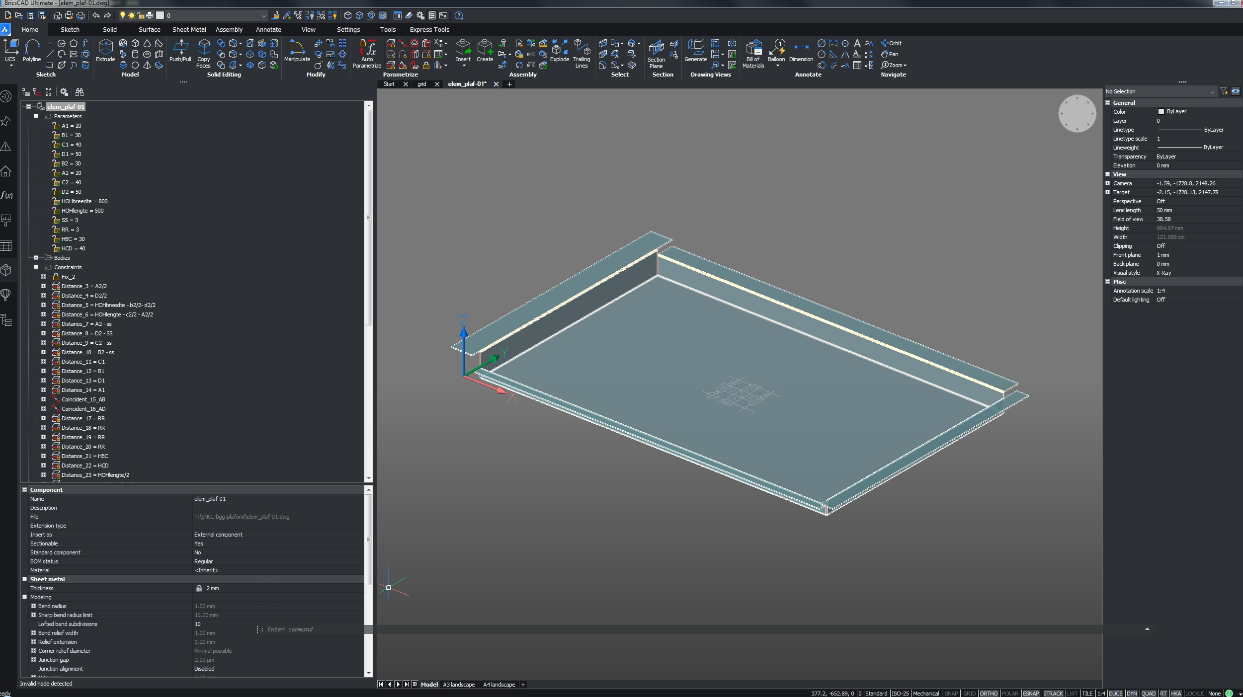
My client wants a ceiling consisting of aluminium pans and most of them are unique in size and height. Base element is an open box with wide flaps.
The idea is to have a parametrized version so it is easy to make different types and make a bill of material for the whole plan (BOM). Flaps height and width can also differ.
The parts will be hanged in a metal framework. In the model i would like to use the origin point of the ceiling part. Due to thickness of metal framework the outside walls of the ceiling part are xx mm offset to the inside of the grid lines
I modeled and added parameters to the design I want but somehow it is not working.
Sometimes one action can be changed and then everything freezes or params turn yellow.
Did try the auto parametrize option without succes
A box without the flaps (modeled and params added in the same way) is working fine.
Any ideas to point me in the right direction ? That is really appreciated.
Regards Harold
bricscad mech v21.2.05
0
Comments
-
Hello Harrold
When the model freezes like you describe it means you have "over-constrained" the model.
This can happen when you have 2 constraints on the same faces each with a different value.
But in your case it's the sheet metal "intelligence" that's conflicting with a constraint.
The sheet metal module adds "invisible" constraints to your model, an example of this is the Thickness.
If you place an additional constraint on the thickness and it conflicts with the thickness of the sheet metal it freezes.
In your specific case it's the junctions that are conflicting with the HOHLengte and HOHBreedte.
If you remove the junctions the model works, but you will need to add constraints to do the work of the juntions that need to be removed.
Succes er mee!
Mvg Robert0 -
Thanks for the input Robert,
due to you message I have been fiddling around and came up with a working version. I guess that the inner bend between vertical and horizontal flange was causing the conflicts with the sheet metal intelligence. Now using the outer edges. The junctions you mentioned are still there but pop up red in the Mechanical Browser.
I really hate workarounds ...... but when the horizontal flange extension meets the edge of the vertical flange it dissolves and cannot be used anymore. I have entered a minimum distance of 0.01 mm
and between the corners (for example B2 and C2 ) a length constraint with the sheet thickness, else they will merge sometimes.
My BOM sheets look marvelous !
I uploaded the file for learning purposes ;o)
Regards,
Harold
PS
Too bad there are no handles available in BricsCAD0 -
Good to hear you got it to work!
I don't have bricscad on the system I'm on right now, but I'll take a look at the model later today!
What do you mean with handles? Bricscad has object handles each object has an identifier called a handle you can view this in the properties window. Or do you mean handles as in handholds/grips library objects?
With kind regards
Robert0 -
I mean the drag handles on dynamic , apologize, parametric blocks. I see bricscad has 2D Dynamic Grips. Then it is easy to adjust the size of a 3D element on for example a grid, now I have to measure where it has to fit in and then enter values in the block parameter.0
