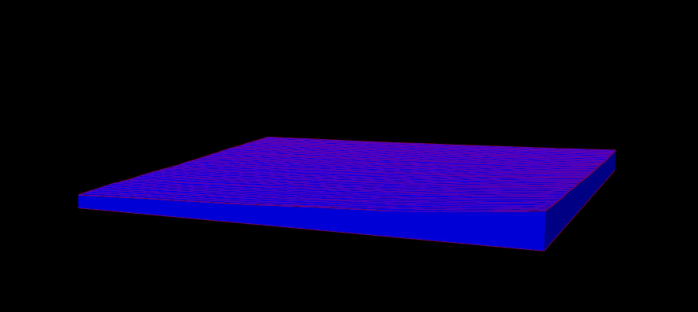
How to Create a Solid Surface from a TIN Surface then Output as STEP File
Please excuse my lack of design knowledge - a Surveyor talking here......
I have to create a CNC file from a survey model which is irregular. It is a bearing plate for a bridge which is attaching to another plate that has been damaged and warped.
I primarily use 12d and have limited knowledge with BricsCAD but I know how to create a TIN Surface in BricsCAD. But I need to make this a solid surface so I can export it as a STEP file for CNC machine cutting.
Does anyone have any knowledge of the process of going from TIN Surface to a solid surface that is "water tight" and then exporting that as STEP format file?
Any light on this would be appreciative.
Cheers
Chris

0
Comments
-
What is your input, what objects are displayed in the screenshot ?
Is this a TIN Surface already or a mesh or what ?0 -
Hello Chris,
Kinda depends on the quality of the model you have.
Sometimes you have to plug some gaps and then stich it together.
You could try the "stitch" command first, select everything and then stitch.
The part is pretty simple so you could measure it, make a 2d sketch from the side and then extrude it.
If you post your DWG here there are lot of people here who would love to do it for you.
0 -
Hi Chris,
If it's a mesh, you use command CONVTOSOLID
If it's a TIN surface, you can use command TINEXTRACT and choose option Solid.
To export to STEP, you will need Communicator on top of your BricsCAD: https://www.bricsys.com/en-eu/communicator/
Kind regards,
Chi-Yan0 -
Thanks for your advice everyone. Its greatly appreciated.
I might just leave the dwg file on here if anybody wants to have a go at it.
I do need to make some drill holes for some bolts and some rebates for the head of the bolts too. But I will work on that today.
Cheers
Chris0 -
Hi Chris,
In attachment, a dwg with the solid object and the exported step-file of it.
Kind regards,
Chi-Yan0 -
Thanks so much Chi-Yan0
-
Hi Chiyan,
I was just wondering if you can create the STEP file again with some added features.
I have updated the drawing which has some clearance holes for some bolts and some tapped holes for some bolts.
The blue lines in the dwg are to M30 tapped holes, the cream lines are to be 32mm clearance holes and the red lines are to be 73mm clearance holes.
What you produced beforehand was perfect!
Cheers
Chris0

