Create an automated snapping object on BricsCAD

Hi to everybody,
I'm Alex, and I'm new on this forum.
I'm using BricsCAD for a while, and I find it really great.
I was wondering if there's the possibility to create functions on the CAD that allows the user to snap an object around the space in precise spaces.
For example, that script should be able, from an insertion point, snap an object into various positions, by e.g. 90 to 90 degrees, and automatically being snapped into the hole.
Here's the file.
Is there a possibility to do it in BricsCAD, please?
Thanks a lot in advance.
Have a Great Day,
Alex
0
Comments
-
Edit: that should give the various possibilities to the user who puts the piece0
-
Hi,
Perhaps worth checking out the BMInsert Command?
https://help.bricsys.com/document?title=_commandreference/CMD_bminsert.html&documentVersion=V22#CMD_bminsert__section_rcg_hst_w4b0 -
Hi Kin, thanks for your answer.
I need to create "something" that limits directions of placing of an object. This to limit placing errors. I really don't know where to start: user have not to insert placing angles, automaticlly, when I rotate the object, the CAD should tell me thanks to this function, the snaps directions I set on the function.
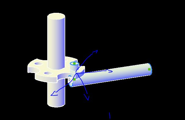
For example by showing directional arrows.0 -
Hi Alex,
This sounds like something "Smart Insert" could be used for.
Smart Insert is something you can add to your components that will allow them to snap together upon inserting them together.
I created an example that I have attached. First thing I did is give it an assembly structure, this is because you need to insert the parts onto each other for this functionality.
"provasnapping" is the main assembly file.
"Vertical" and "Horizontal" are the sub-components that are inserted into the assembly.
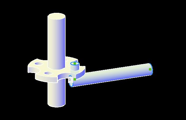
The way it works is that you place a point. (POINT command)
Then you draw a line from the point in a certain direction. (In this example it can be placed in the hole of your model)
Also repeat this on another part. (In this example on the shaft passing through the hole)
These points and lines need to be on a specific layer to gain the "snapping" function. The layer needs a name and then a suffix of "_CONNECTION", in my example I named the layer "Snap_CONNECTION" and placed the point and line in this layer.
(Keep in mind that the layer names need to be identical between the parts you want to connect)
Then you can use the BMINSERT command to insert the parts. If the assembly file is empty you can click to place it normally.
For the 2nd part you need to use the insert command and use the Ctrl toggle option for "Smart Insert". (While inserting the part press Ctrl two times)
Then when you hover over the other part you should see them connect.
Please take a look at the video and files I shared and let me know if this is what you are looking for.
EDIT: The models were made using V22, and at least V21 is needed for the Smart Insert feature.0