Cut Plain Area into TIN Surface
in 3D Modeling
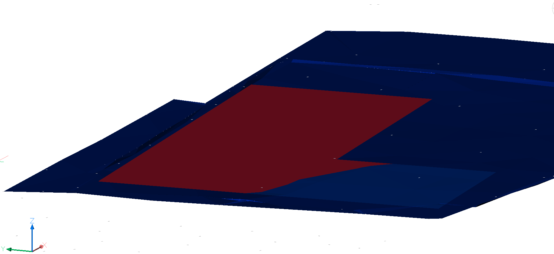
I want to join two surfaces:
1. TIN Surface with a slight slope (blue)
2. A plain/level TIN Surface with a fixed height (red)
I want to change the blue surface, so that the area where the red surface is lower than than the blue area is cut out, but the area where the red surface is higher does not change.
With tinmerge, the resulting TIN surface will be elevated where the red surface is higher, which I do not want.
I tried to create a grading, but I was not able to merge it with the tin surface, so that the resulting object would be a surface TIN again.

0
Comments
-
I am not a civil engineer and there is probably a better way to do what you want....
I tried the following steps and succeeded to accomplish the task .
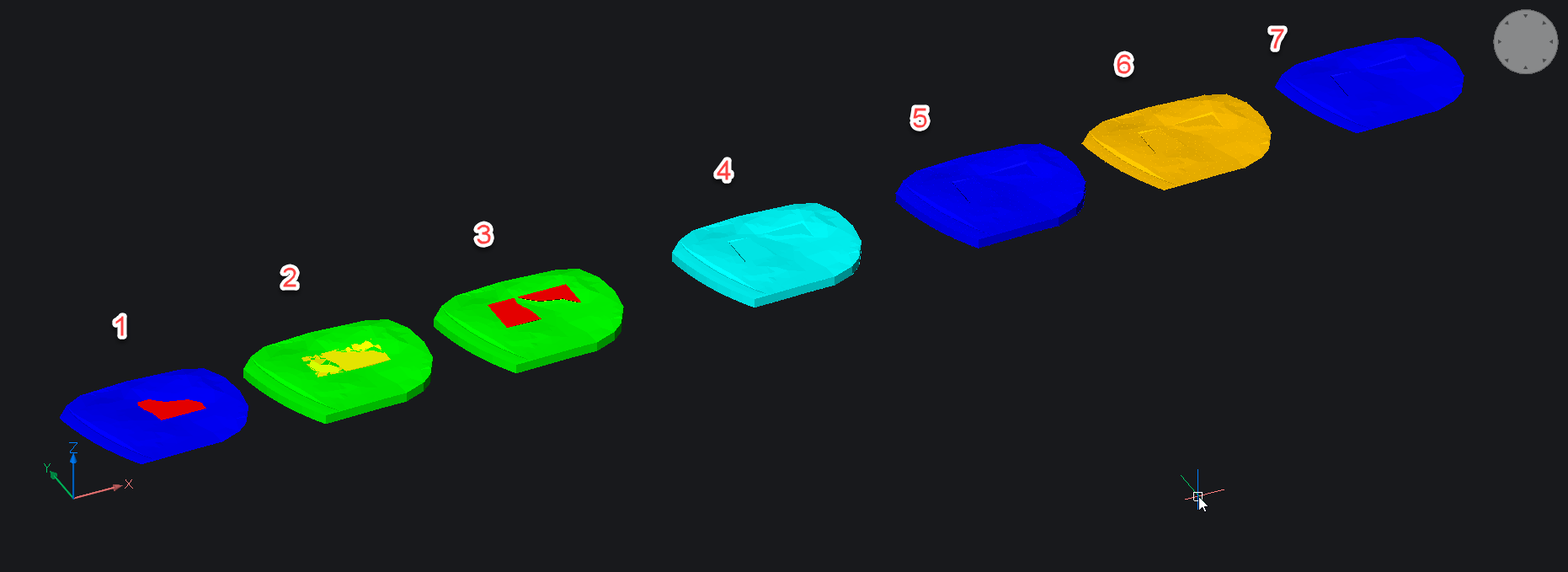
Here is a screenshot for clarity
Step 1.
Two TIN surfaces are used, a blue one (the terrain) and a red one (the plateau), which is in the middle above the terrain. The red area above terrain should not be part of the the final TIN while the red areas below the terrain should be cut out from the blue terrain TIN.
Step 2.
Use the TINEXTRACT command with the Solid option to produce a terrain solid (green).
Extract [Mesh/Solid/Points/Faces/Contours/Border] :
Use the TINEXTRACT command again with the Solid option and the between Surfaces option to produce the solid between the terrain and the plateau TINs.
Step 3.
Use the SUBTRACT command to subtract the in between solid from the terrain solid,
then trace the contours of the two horizontal excavated areas and produce two extruded (red) solids with -45 degrees taper angle to simulate gradings.
SUBTRACT these solids from the terrain solid
Step 4.
Use the CONVTOMESH command to create a MESH from the terrain solid.
Step 5
EXPLODE the MESH in 3DFACES
Step 6-7
Create a TIN surface from the 3DFACES using the TIN command with the Faces option.
select entities to create TIN surface or [Import from file/place Points/create from Faces/create from Point Cloud/cLip polygon/selection options (?)]:
...hope this is the TIN surface (final blue) you wanted!
you find the DWG file attached.0 -
an additional note!
In Step 6 all side and bottom 3DFACES should be deleted !
It is easily done by selecting them with a crossing window from a side, front or back view...
0 -
Thank you very much for answer. This helps a lot!0
-
I encounterd an error at step 3: new ef_int outside edge. This could be worked around in my case (the plateau is plain) as follows:
- Create the outline of the plataue and set the z-value to the required height
- Select this line and use dmextrude with the angle for the grading and any height
- Use ConvToMesh on the Terrain Solid
- Use Slice to cut the plateau solid in two piece along the terrain
- Delete the unwanted part of the plateau solid
- Use ConvToMesh on the Plateau solid and explode it to 3dFaces
- Delete the "lid" 3dFaces and create a tin surface
- Use TinMerge to Merge with terrain, where the terrain is teh base surface
0 - Create the outline of the plataue and set the z-value to the required height
