Create Bodies in mechanical

We can use the BC_SUBTRACT layer to automatically create holes and cutouts in assemblies.
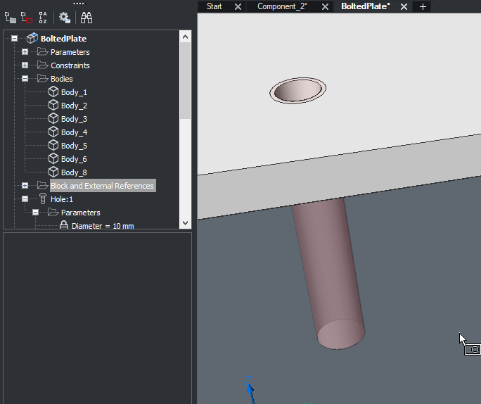
In the BoltedPlate.dwg file for the BIM-Training-V20 there are multiple bodies inside used for making the holes once it is used.
How do we create these "Bodies" in a mechanical context?
In the BoltedPlate.dwg file for the BIM-Training-V20 there are multiple bodies inside used for making the holes once it is used.
How do we create these "Bodies" in a mechanical context?
0
Comments
-
Hello Linneman.
To make your own BC_Subtract bodies there are 2 conditions.
1. It has to be a block
2. The block needs to be in the Layer BC_Subtract
So make any shape you like and save it as a block in your drawing.
Load a BC_Subtract hole from the library (this way the layer BC_Subtract is added to your drawing).
Then remove the hole again.
Now change the layer of the block to BC_Subtract.
Now you have a custom hole. If you want you can parameterize it or add it to the library.
If the new custom hole is not subtracting run the "BMLINK" command.
* Note there is also the "BC_JOIN" layer to add stuff.
0 -
Hi Linnemann!
These layers work the same way with the Mechanical license as they do in BIM. Meaning that they need to be blocks, with a volume on the layer BC_SUBTRACT. And when inserted onto a solid it will subtract the volume you created.
More generally speaking on how Mechanical parts work you can find below:
In a Mechanical context the bodies that appear in the Mechanical Browser panel are simply 3D solids with some constraints attached to them. Meaning that the bodies themselves are just simple 3D solids.
In the Mechanical license you are given the opportunity to add more information to these solids by making them into Mechanical Components. This can currently be done with the help of the commands BMFORM and BMMECH.
BMFORM will ask you to select a 3D solid to form as a Mechanical Component, allowing you to add material information, set BOM status, see the part in the BOM Manager panel, add custom properties, etc. within the formed component.
BMMECH will initialize a mechanical structure in the file you run the command in. Allowing you to add the information mentioned above also.
After this you can make a new file and use the BMINSERT command to insert Mechanical Components, to form a mechanical assembly.
If you want more information on these commands, I suggest looking them up on our help page as there is a lot of useful info there. Below I will add links to the commands mentioned:
https://help.bricsys.com/document/_commandreference--CMD_bmform/V22/EN_US?id=165079057077
https://help.bricsys.com/document/_commandreference--CMD_bmmech/V22/EN_US?id=165079057884
https://help.bricsys.com/document/_commandreference--CMD_bminsert/V22/EN_US?id=165079057480
Also it might be helpful to take a look a the Mechanical training found on "lessons.bricsys.com":
https://lessons.bricsys.com/p/bricscad-mechanical-essentials
I hope this helped!0 -
Thank you Robert and Fredrik for the input.
I had a chat with support and really the easiest way to get the bodies listed in the Mechanical Browser is to create a Parameter/Constraint to the body and then delete it again if not needed.
I Think it would be good to have an option to show the solids in the mechanical browser for easier selection for example for boolean operations and other stuff.
I will make a feature request for just this.0