Geometric & Dimensional Constraint help

I am trying to create a parametric drawing where one section is kind of a mirror image of another but offset a certain amount and rebated a set distance.
The attached drawing might explain it better than my words
The height at the front and back are adjustable, as is the distance between them.
I can't figure out what I need to add, either geometrically or dimensionally, to make this work as the mirror angle will change when you alter the front or the back height.
The following link will give you an idea of what I am trying to achieve https://diecuttemplates.com/dielines/51870/tray-boxes-becf-21b05
Please feel free to ask any questions if I haven't explained it very well.
Any help would be greatly appreciated, I'm hoping it is something simple I am overlooking.
0
Comments
-
Will the mirror line always be a line that's offset 2 mm from the line connecting the tops of the front and back?David Waight said:... the mirror angle will change when you alter the front or the back height. ....
0 -
Hi Anthony,
Sadly no, as the distance between the two parallel lines is dependent on the thickness of the material.
It is however always in the centre of the two parallel lines.0 -
So, instead of 2 mm, that offset distance will always be the thickness of the material? Or some multiple of the thickness?0
-
Hello David ,
What you are trying to do is possible but very difficult in parametric 2D.
The chance of over constraining and thus breaking it are also very high.
It becomes a lot easier to do when you use the Sheet Metal module an try to parameterize that.
Do you have BricsCAD mechanical?0 -
Thanks for the replies,
@Anthony Apostolaros If you interrogate the drawing you will see that there is a dimensional constraint that is 2.66 times the Material thickness.
@Robert I'm afraid I don't have Mechanical; what does it have constraint-wise that is different from Pro?0 -
@David Waight It has the sheetmetal module where you can model your cardboard in 3D.
You can then add 3D constraints to it to change the size and shape. It just makes it easier.
0 -
@David Waight Ok I think I got it to work like you want it.
I added a "fix" constraint (its always good to add this, because it gives you a unmovable point in your drawing). I added some missing constraints.0 -
Is this something that rotate3d would do better. Make flat pattern then rotate3d around 2 pts/edge.
End up with 2d/3d object. If you use pface this will make say pline a non transparent object.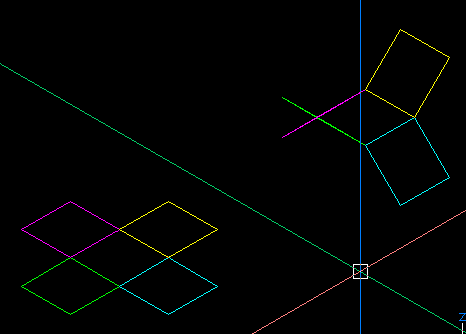
0 -
OK, so I have had another go at this between jobs and have made a bit more progress.
I added some extra entities (on layer 0) that create reference sizes for the dimensional constraints to use.
Probably not the best way of doing it, it would be easier if I could use dimensions as a reference, rather than lines.
I wasn't sure what the "geometry-driven" option was when you right-click a dimensional constraint in the Parameters & Constraints (legacy) Palette.
It doesn't seem to be in the new Parameters & Constraints Palette.
It would have been nice if I could create something like a geometry-driven constraint so the drawing drives the constraint and I could then reference it to get some of the distances I needed.
Does any of the above make sense?
Anyway, I have attached the drawing again so you can perhaps see what I am trying (badly) to explain.0

