Induction Motor Starting Voltage Drop Examples BricsCAD V22.2.05 InPower Ver. 1.02.8

Induction Motor Starting Voltage Drop Examples
Using BricsCAD V22.2.05 InPower Ver. 1.02.8
Oct. 2022
Large motor loads can cause significant voltage drop when starting. Typical motor starting currents can be 6.0 times the motor’s rated full load current. Motor starting current is mostly inductive and the starting power factor is typically in the range of 20%. Electrical codes can put limits on starting voltage drops for electrical fire pumps. The 2020 NFPA 70 NEC limits the starting voltage drop for fire pumps at 15% maximum at the pump controller. A motor start acts like a high impedance three phase short circuit on the electrical system.
Calculating the motor starting current involves the motor code letter determined by the manufacturer. Motor nameplates have a code letter that describes the locked rotor KVA per horsepower for the motor design. Table 1 shows the code letter and the associated KVA per horsepower.
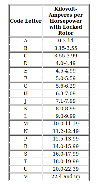
Table 1 is used to calculated the motor starting current and impedance. For example, a 100HP 75KW 124A 460V motor with Code letter G would have a starting KVA range of 5.6 to 6.29 KVA per horsepower or,
6.29 * 100 = 629 KVA at 460V or 789.5 Amps maximum starting current, or 789.5/124=6.37 times the full load amps. Calculating the starting impedance Zln=Vln/A = 277V/789.5 = 0.351 ohms at 20% power factor. Or, 0.702 + j0.3438 ohms.
An across the line full voltage start would cause 6.37 times the motor’s full load current to flow. This large current can cause significant voltage drop in the electrical power system transformers and cables.
Several methods can be used to reduce the motor starting current. Figure 1 and Table 2 shows the reduced starting current vs speed curves for wye delta, auto-transformer, part winding and primary resistor starting methods. Electronic soft starting also exists and prevents the surge current at 90% rated speed. See Figure 2.
A wye delta starter changes the motor winding configuration from wye at starting to delta when running at approximately 90% rated speed. This wye configuration reduced the applied voltage to the motor windings to 1/sqrt(3) = 58% of rated voltage. The Wye configuration also increases the input impedance of the motor by configuring it in wye. For a balanced load, 3.0*Zwye = Zdelta. For the above motor Zwye = 277V/789.5A=0.351 Ohms input impedance looking into the motor. Zdelta = 3.0 * Zwye = 1.05 Ohms. The wye delta starter reconfigures the delta connected 1.05 Ohm motor to wye. The line starting current will now be Istarting = (480V/sqrt(3)) / 1.05 Ohms = 263.81 A or 100 * 263.81/789.5 = 33%. The Wye configuration reduces the starting amps by 1/3 = 33%. Starting torque is also reduced by 33%.
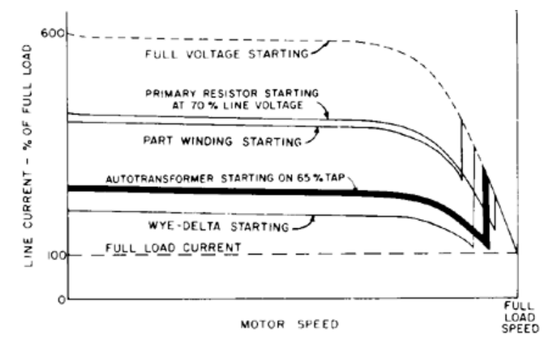
Figure 1.
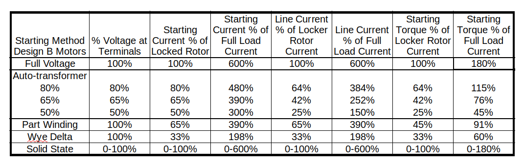
Table 2.
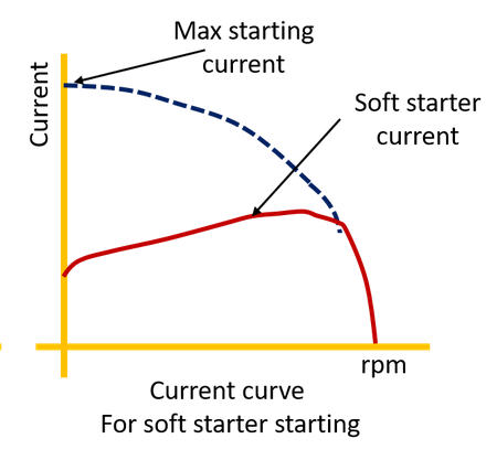
Figure 2.
Example 1, Wye Delta Starter
InPower three phase short circuit is used to simulate a Wye Delta reduced voltage starter for a 150 horsepower 460V motor Code letter F, 5.59 KVA/HP and 180 Amps full load. The starting amps are calculated at (1000*5.59*150 / 3) / (480/SQRT(3)) = 1008.56 Amps. The Wye Delta Starter reduces the starting amps to 33% of the 1009 Amps, or 336 Amps starting current. Calculating the starting impedance: Zln=Vln/Amps= 277/336= 0.824 ohms at 20% power factor. Zln=0.1648+j0.8077 ohms.
To simulate the motor start in InPower, add a bus near the motor load. Connect this new bus with a Line with impedance equal to the calculated motor starting impedance Zln. Change the FAULTBUS in the SYSTEMBASE block to the new bus number. Run the three phase fault to get the voltage drop throughout the network. The voltage at the motor terminals during starting is 95.4%.
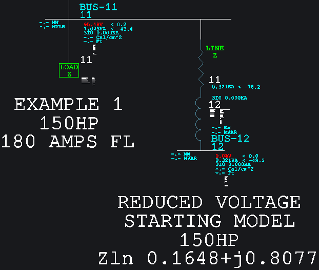
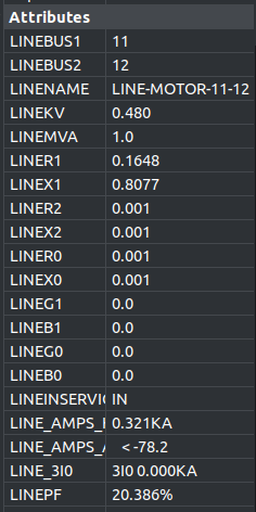
Figure 3.
Using BricsCAD V22.2.05 InPower Ver. 1.02.8
Oct. 2022
Large motor loads can cause significant voltage drop when starting. Typical motor starting currents can be 6.0 times the motor’s rated full load current. Motor starting current is mostly inductive and the starting power factor is typically in the range of 20%. Electrical codes can put limits on starting voltage drops for electrical fire pumps. The 2020 NFPA 70 NEC limits the starting voltage drop for fire pumps at 15% maximum at the pump controller. A motor start acts like a high impedance three phase short circuit on the electrical system.
Calculating the motor starting current involves the motor code letter determined by the manufacturer. Motor nameplates have a code letter that describes the locked rotor KVA per horsepower for the motor design. Table 1 shows the code letter and the associated KVA per horsepower.
Table 1 is used to calculated the motor starting current and impedance. For example, a 100HP 75KW 124A 460V motor with Code letter G would have a starting KVA range of 5.6 to 6.29 KVA per horsepower or,
6.29 * 100 = 629 KVA at 460V or 789.5 Amps maximum starting current, or 789.5/124=6.37 times the full load amps. Calculating the starting impedance Zln=Vln/A = 277V/789.5 = 0.351 ohms at 20% power factor. Or, 0.702 + j0.3438 ohms.
An across the line full voltage start would cause 6.37 times the motor’s full load current to flow. This large current can cause significant voltage drop in the electrical power system transformers and cables.
Several methods can be used to reduce the motor starting current. Figure 1 and Table 2 shows the reduced starting current vs speed curves for wye delta, auto-transformer, part winding and primary resistor starting methods. Electronic soft starting also exists and prevents the surge current at 90% rated speed. See Figure 2.
A wye delta starter changes the motor winding configuration from wye at starting to delta when running at approximately 90% rated speed. This wye configuration reduced the applied voltage to the motor windings to 1/sqrt(3) = 58% of rated voltage. The Wye configuration also increases the input impedance of the motor by configuring it in wye. For a balanced load, 3.0*Zwye = Zdelta. For the above motor Zwye = 277V/789.5A=0.351 Ohms input impedance looking into the motor. Zdelta = 3.0 * Zwye = 1.05 Ohms. The wye delta starter reconfigures the delta connected 1.05 Ohm motor to wye. The line starting current will now be Istarting = (480V/sqrt(3)) / 1.05 Ohms = 263.81 A or 100 * 263.81/789.5 = 33%. The Wye configuration reduces the starting amps by 1/3 = 33%. Starting torque is also reduced by 33%.
Figure 1.
Table 2.
Figure 2.
Example 1, Wye Delta Starter
InPower three phase short circuit is used to simulate a Wye Delta reduced voltage starter for a 150 horsepower 460V motor Code letter F, 5.59 KVA/HP and 180 Amps full load. The starting amps are calculated at (1000*5.59*150 / 3) / (480/SQRT(3)) = 1008.56 Amps. The Wye Delta Starter reduces the starting amps to 33% of the 1009 Amps, or 336 Amps starting current. Calculating the starting impedance: Zln=Vln/Amps= 277/336= 0.824 ohms at 20% power factor. Zln=0.1648+j0.8077 ohms.
To simulate the motor start in InPower, add a bus near the motor load. Connect this new bus with a Line with impedance equal to the calculated motor starting impedance Zln. Change the FAULTBUS in the SYSTEMBASE block to the new bus number. Run the three phase fault to get the voltage drop throughout the network. The voltage at the motor terminals during starting is 95.4%.
Figure 3.
0
Comments
-
Example 2, Fire Pump Voltage Drop
NFPA 70 NEC limits the voltage drop for fire pumps to 15% at the fire pump controller line terminals. BricsCAD InPower is used to design the system. The existing electrical service to the building is 208V 3 phase 4 wire with a 100 KVA transformer at 3%Z. The proposed fire pump is a 100HP 75KW 208V 3 phase 273 Amps with code letter G 6.29KVA/HP. The starting current is (1000*6.29*100/3)/120V=1746 Amps. The starting impedance is calculated as Zln=120/1747 = 0.0674 ohms at 20% power factor = 0.0137+j0.0674 ohms.
To simulate the motor start in InPower, add a bus near the motor load. Connect this new bus with a Line with impedance equal to the calculated motor starting impedance Zln. Change the FAULTBUS in the SYSTEMBASE block to the new bus number. Run the three phase fault to get the voltage drop throughout the network. The voltage at the motor terminals during starting is 80.4%. This is an unacceptable voltage drop. A reduced voltage starter is needed.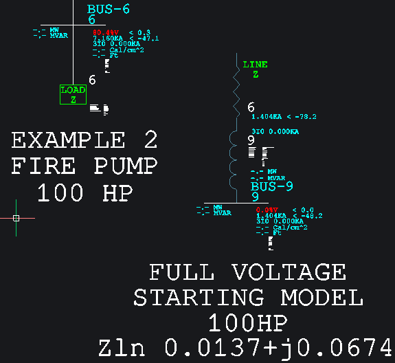
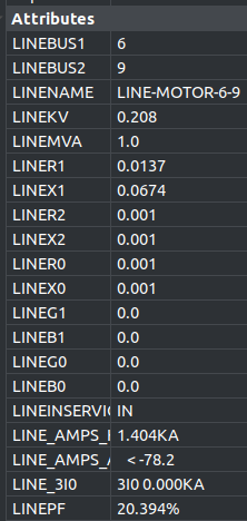
Figure 4
0 -
Example 3 900HP 4.16KV Code letter F motor Start With 25MWA generator
The unsaturated transient reactance X’d is used as the positive sequence reactance. The subtransient reactance X’’d is used for short circuit simulations lasting less than 4 cycles.
Motor starting Amps = 698A at 20% PF
Calculated Z fault = V/I = 2400V/698A = 3.37 Ohms
Zf = 0.688+j3.37 Ohms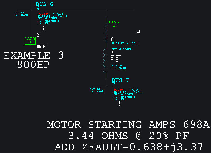
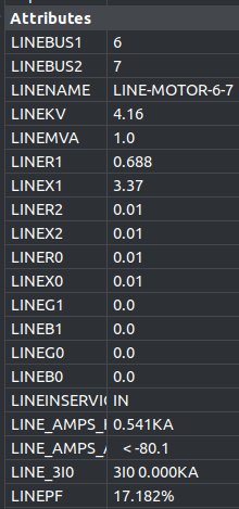
Figure 50