Problems with polyline arc bulge going the wrong way

I have a client I do a bit of work for who complains that sometimes my DXFs don't load properly.
Here is a photo from his software: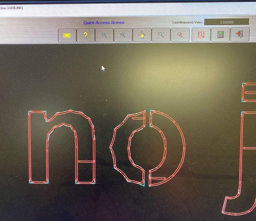
The file is of polylines made using the join command.
As you can see, some of the letters seem to have the curvature reversed. When I explode the polylines the curvature becomes normal.
This has happened on several jobs recently.
My workflow is as follows:
Create text or vector objects in CorelDraw
Save as DXF
Convert splines in the drawing to polylines with lines and arcs (using SplineEdit software)
Open in BricsCad V22
Save as DXF (version: ASCII2000)
Edit in BricsCad V22
Send to client - file looks perfectly OK to me but not to him, as you can see.
My workflow as above has not changed in 10 years. Prior to this I was using Autocad 15
I have tried changing the direction of polylines but that doesn't seem to do anything.
This only started happening recently.
I realize this could be a problem at his end, but it is a bit of a mystery!
0
Comments
-
If you search here there is text2geom by Seant, there is now a Bricscad version. This may help the problem. Will find post so give credit to author who made the Bricscad version0
-
Thanks for your reply. Unfortunately it's not just text but also arcs and lines that misbehave sometimes for no obvious reason - except they are in polylines.0
-
Since DXFs are kind of human readable, I would suggest using WinDiff to compare output files0
-
Things worth checking:
- Make sure the files you send out have the same file version as before.
- Check the polyline type: "Polyline" ("Light") vs. "2D Polyline" ("Heavy").
- Check the direction of the generated polylines and compare with older files where the issue did not occur. It may be that the receiving software assumes a counterclockwise (or clockwise) direction.
- Check the Normals of the polylines.
0 - Make sure the files you send out have the same file version as before.
-
I wouldn't be surprised if it was the software your client is using.
I create .dxf files from Bricscad and send them to a CNC machine; within the routine, I have the file can be rotated and mirrored before exporting.
When I send some files with polylines to the CNC program they are sometimes not rotated or mirrored but look fine in Bricscad or other programs that can read .dxf files.
If I use TXTEXP on text in Bricscad, then the CNC program gives me lots of lines that run across the lettering similar to your original screenshot, I have to explode them before I export my dxf to get rid of them.
So what is the program your client is using and have they updated it recently?
There are a lot of libraries out there that read .dxfs but if they aren't based on Autodesk or ODA libraries they will more than likely give issues.
Regarding your workflow (I know you have now added that arcs and lines are now affected) but can you not convert the text to curves in Coreldraw (Ctrl + Q) and then use FLATTEN in Bricscad to convert to Polylines?0 -
Thanks for your responses.
Check the polyline type: "Polyline" ("Light") vs. "2D Polyline" ("Heavy"). - not sure how to do this?
Check the direction of the generated polylines and compare with older files where the issue did not occur.
It may be that the receiving software assumes a counterclockwise (or clockwise) direction. Will try this
Check the Normals of the polylines.not sure how to do this?
My client asks for ASCII 2000 DXF which is 22 years old after all. However it has worked well until very recently.
The flatten command works OK except polyline curve segments are tiny: 0.8 mm. SplineEdit does much better than that, but it is old software also.
With the polyline light/heavy setting - does saving in ASCII 2000 DXF force the polylines to be heavy on save?
0 -
Select the polyline and see what the Properties panel calls it, and maybe what the LIST command calls it.jeremiawuzza said:....
Check the polyline type: "Polyline" ("Light") vs. "2D Polyline" ("Heavy"). - not sure how to do this?
....
With the polyline light/heavy setting - does saving in ASCII 2000 DXF force the polylines to be heavy on save?
- A "new" or lightweight polyline is now called "Polyline" in the Properties panel, though it's still called LWPOLYLINE by the LIST command.
- A "classic" or heavyweight polyline is now called "3D Polyline" in the Properties panel, though it's still called POLYLINE by the LIST command.
I think the new lightweight polyline was introduced in R14 (1997).
0


