Easiest Way to get a Cut through TIN Surface
in 3D Modeling
Hi,
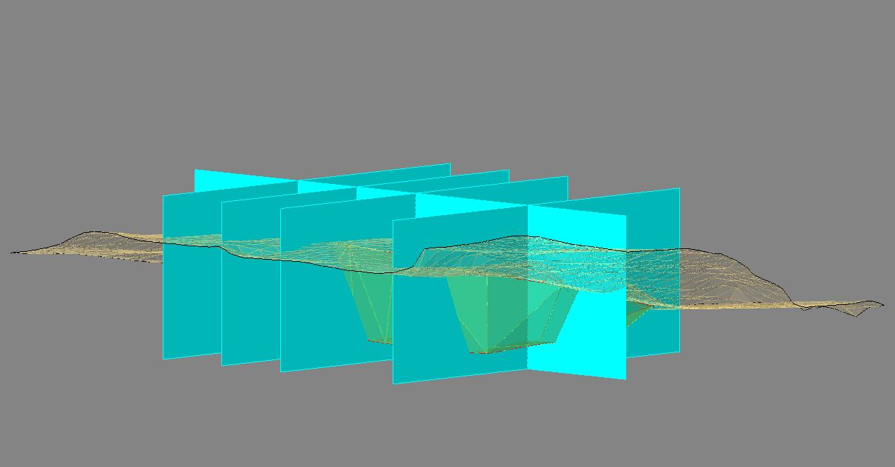
I want to draw 6 cuts (blue in img) through two tin-surfaces (green and brown in img). What is the easiest way to day this?
Thank you.
I want to draw 6 cuts (blue in img) through two tin-surfaces (green and brown in img). What is the easiest way to day this?

Thank you.
0
Comments
-
Hi,
If you really want to cut meaning Slice the TIN surface follow the steps :
1. TIN surface
2. Explode the TIN 2 times to get a polyface-Mesh
3. Use CONVTOSURFACE command to convert the PfaceMesh to a ACIS Surface
4. Use the SLICE command and an extruded Surface to slice the ACIS Surface to 2 surfaces
5. Use CONVTOMESH command to convert the 2 surfaces to meshes
6. Explode the meshes to 3DFACES
7. Use the TIN command to produce 2 TIN surfaces by selecting the 3DFACES from (6)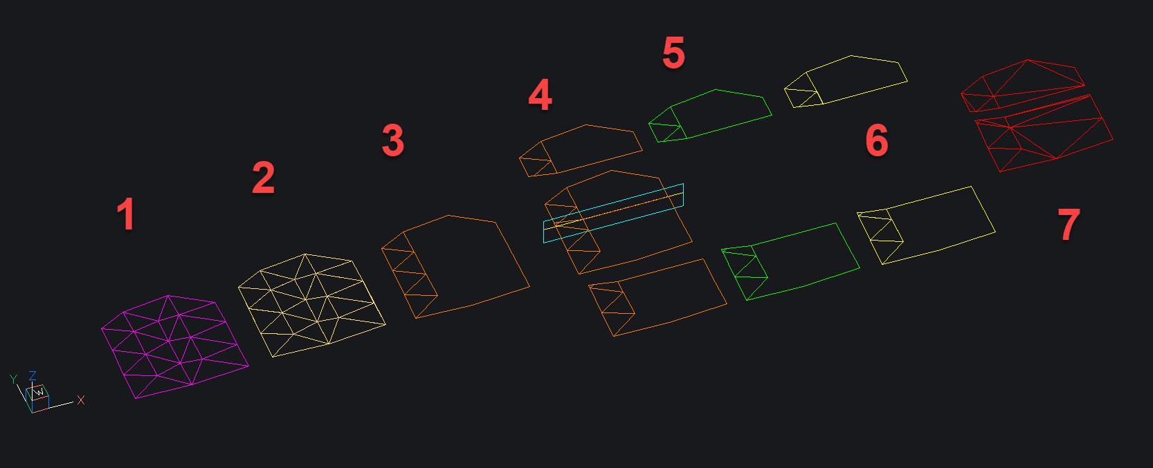
0 -
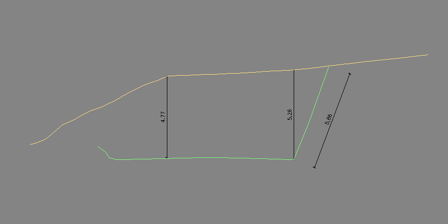
Thank you for your very good answer! However, I do not want to cut the tin-surface, rather than produce a view of the tin surface along an axis which a can measure (see image).
0 -
1.Use the TINEXTRACT command to produce a Solid between the 2 TIN Surfaces
: TINEXTRACT
Select TIN surface [selection options (?)]:
Extract [Mesh/Solid/Points/Faces/Contours/Border] : S
Enter vertical offset or select [between Surfaces/Elevation] <1.0000>: S
Select second TIN surface [selection options (?)]:
1 entities extracted..........
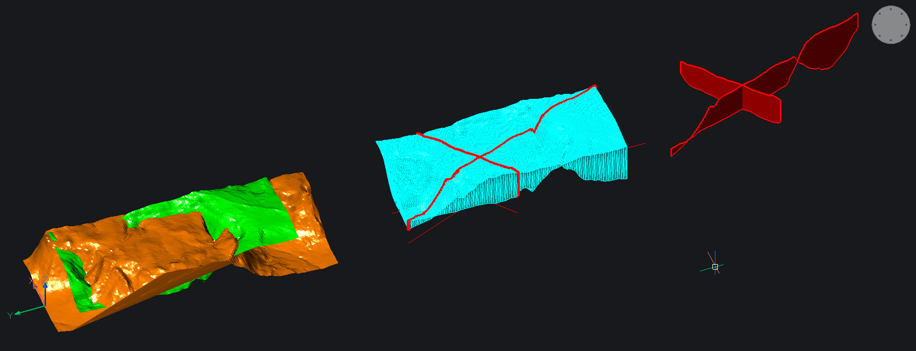
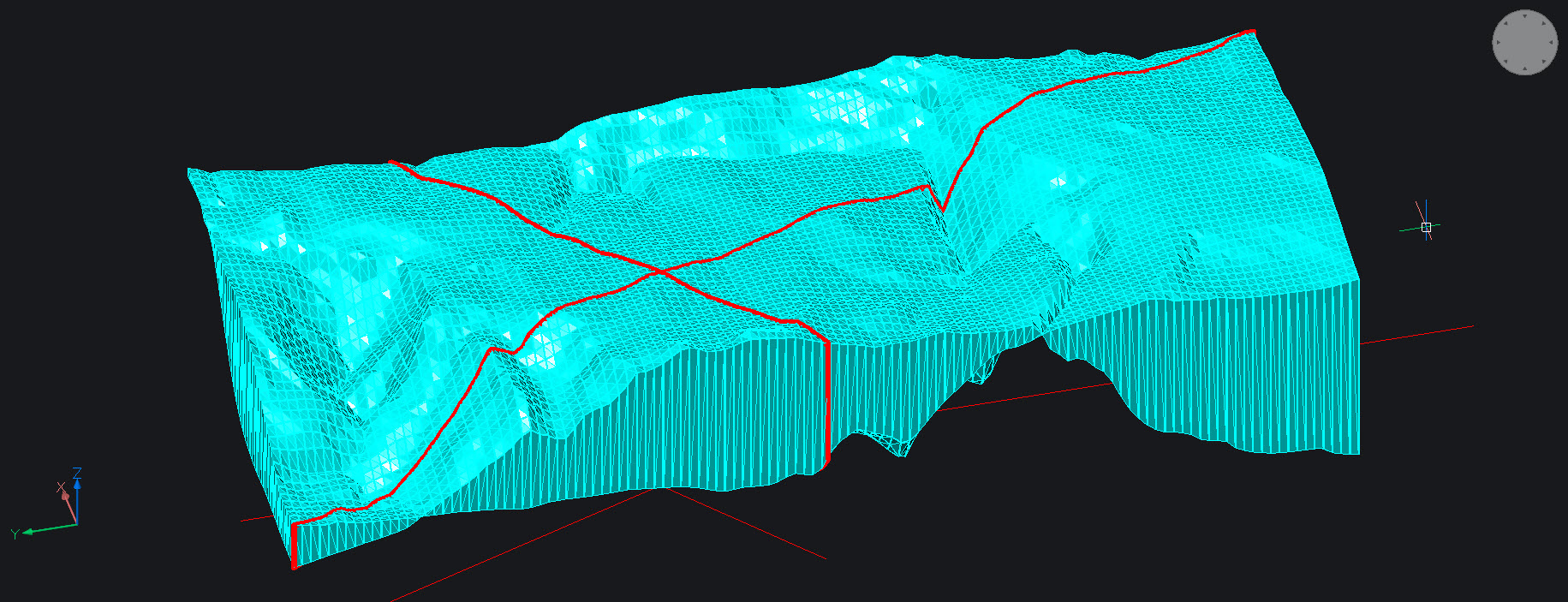
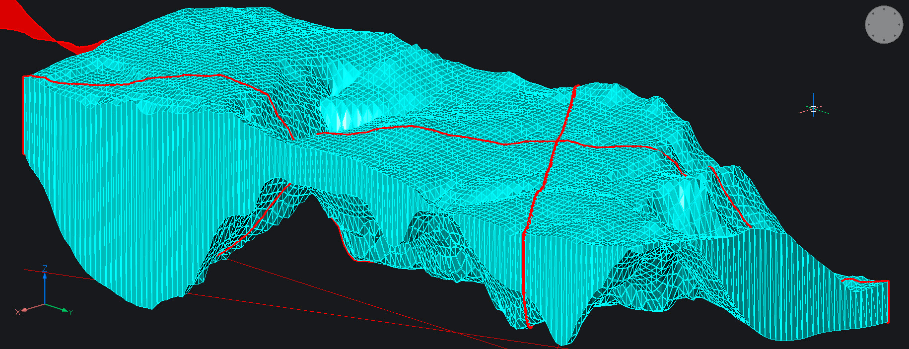
2. Use the SECTION command to section the Solid (cyan) as required......
The created Sections of the in-Between Solid are REGIONS and can be further exploded to curves...splines if required.
You can then measure as wished .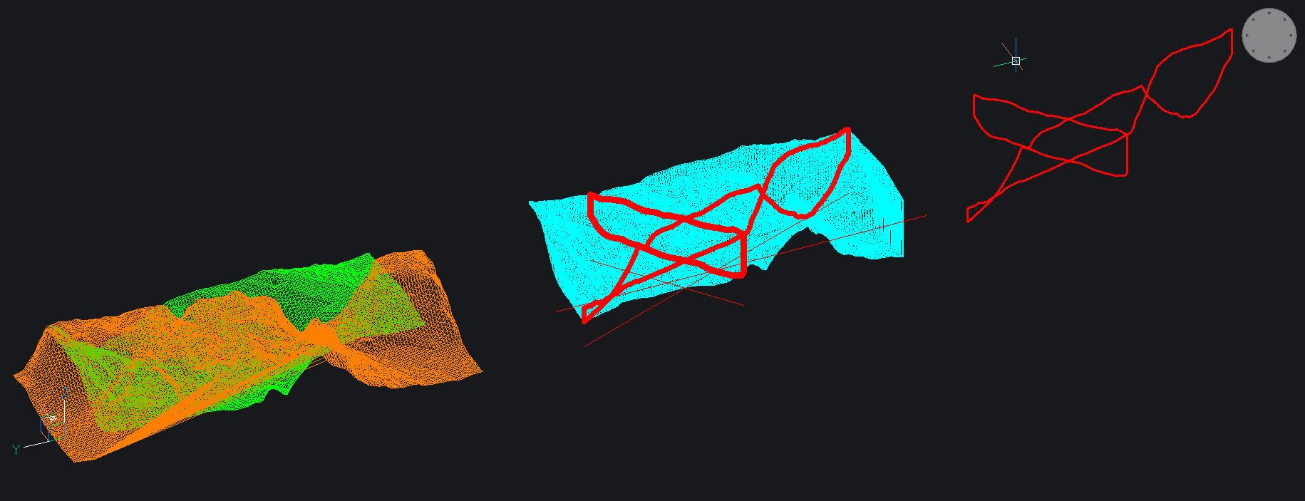
0 -
Some Screenshots of the resulting solid and 2D profiles....
0 -
Why not create a vertical alignment? To do this:
- Use the ALIGNMENTLINE command and use the option to Create new alignment. Pick two points in the plan view where you want your section to be, crossing your TIN surface.
- Use the ALIGNMENTVIEW command to select your Alignment line, then your TIN surface. Then pick a point somewhere in the plan view to place your section.
Regards,
Jason Bourhill
BricsCAD V23 Ultimate
CAD Concepts0 - Use the ALIGNMENTLINE command and use the option to Create new alignment. Pick two points in the plan view where you want your section to be, crossing your TIN surface.
-
Thank you. My problem with ALIGNMENTLINE and ALIGNMENTVIEW was that I could only select one TIN Surface and not two. Is there a way to show two or more surfaces?0
-
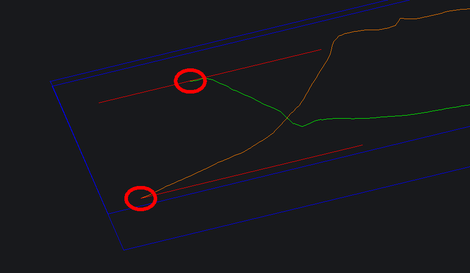
You can create 2 Alignmentlines superimposed in 2 different Layers in order to be able to select them and 2 Alignmentviews, which always have a frame with identical Length , as far as the alignment lines have the same length !
In order to correlate the two alignment views, the height difference of the 3D alignments is required .
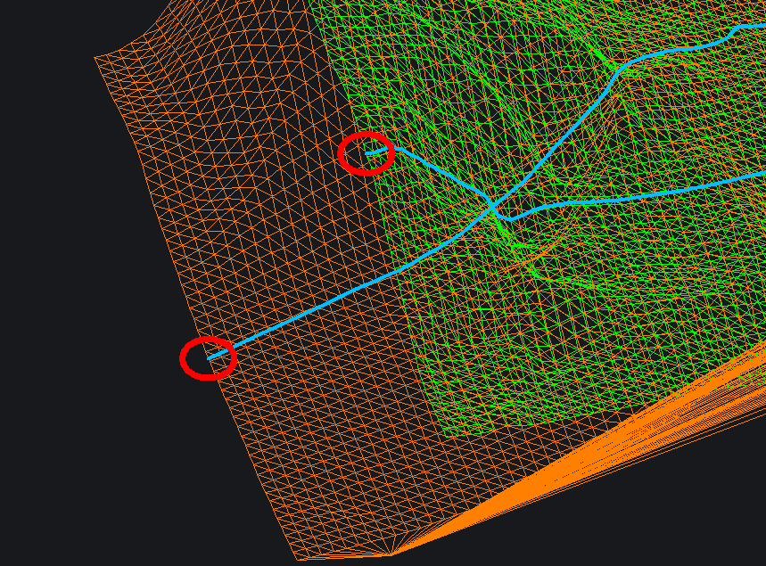
The height difference of the start Points for example (2 red circles) can be used to superimpose and correlate the profiles !
Just use the lisp code to get the height difference of the start points to be used for moving the alignment views to place.....
: (setq h2 (caddr(cdr(assoc 10 (entget(car(entsel "Select Startpoint of first 3D Alignment:")))))))
Select Startpoint of first 3D Alignment: 6423.53469688727
: (setq h1 (caddr(cdr(assoc 10 (entget(car(entsel "Select Startpoint of second 3D Alignment:")))))))
Select Startpoint of second 3D Alignment: 5869.64953532316
: (setq dif (- h2 h1))
553.885161564111
Use !dif as move distance to superimpose the 2 alignment views and the command MOVE.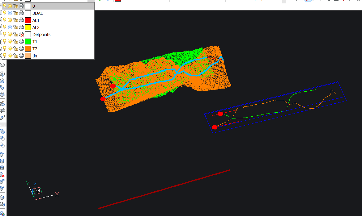
0 -
...by using the lisp code, select the 2 circles of the 3d alignments.....
 0
0 -
Well, one should read carefully the documentation...me too !

The command ALIGNMENTEDIT does it all .
https://help.bricsys.com/document/_guides--BCAD_civil_tools--GD_editingalignments/V23/EN_US?id=165079142328
A second TIN or more can be added to any Alignment View....
: ALIGNMENTEDIT
Select horizontal or vertical alignment [selection options (?)]:
Edit alignment options [Continue with Pi/Delete Element/Add Pi/Remove Pi/change Tin surface/Add Station equation/Remove Station equation]: T
Select TIN surface to add [selection options (?)]:
0

