Bugs in V20 constraints and parameters?

Incidentally, hello to my friends here. I've been away for a long time. I was afraid I was going to have to retire from CAD due to health problems (eyesight and other issues), but I am fighting that.
Comments
-
Hello Jim,
I have never encountered problems with the 2D constraints in V20.
Could you post a drawing you made? I will install V20 and see if I encounter the same problem.
With kind regards,
Robert0 -
Thank you for the kind offer Robert. Here is the file I created and saved based on the youtube video I mentioned previously. For some reason when I open the file today, the geometric and dimensional constraints aren't visible. I tried to make them appear with Show/Hide Constraints, but they don't appear. .They were there when I saved the file yesterday. The author of the video shows constraints in the properties menu. I could not find them there either.Robert said:Hello Jim,....
Could you post a drawing you made? I will install V20 and see if I encounter the same problem.
With kind regards,
Robert
0 -
Hi Jim,
I opened your file in V20 pro and double clicked on one of the lines and the Block Editor opened and I was then able to see all your constraints (press show all on the geometric and dimensional constraints menus if you can't). I added vertical and horizontal constraints to all the lines and this enabled the lines to all stay in position relative to each other (right click on a parameter in the Parameters & Constraints Palette and click Animate) and then save the changes to the block again.
Not sure what you want to do after that as I haven't watched the video you mention.
Hope that helps.0 -
Robert,
I'd be surprised if you were able to replicate the flaky behavior I've seen, because it's likely specific to my machine or Bricsys installation. So rather than waste time searching for that, would you consider instead, just giving me some general guidance on constraints? I originally got interested in the subject when I saw a video on youtube showing how you could create custom cartons from flat cardboard. I figured if I could create a constrained CAD drawing I could make a template for any height, width or length carton I wanted. I imported the image the author provided, then drew my outline on top of the image. I then started applying geometric constraints, followed by dimensional constraints. Every which way I turned, the application kept telling me the drawing was over-constrained.
What is the proper way to do this? Do I start by applying vertical and horizontal constraints to each vertical and horizontal line? Or should I use a bunch of parallel and right angle constraints? What else do i need? Attached is the template I created on top of the author's picture, as well as his document that shows the formulas for the segment lengths. Please forgive me if it sound like I'm trying to get you to do my work. I just don't understand how to properly constrain something like this.
Thanks for your tiem0 -
Jim,
Funnily enough this is what I make for a living and the reason I bought Bricscad is because of the parametrics :-)
I don't have a complete carton like your drawing but I do have a base and the top separately as I make lots of different styles and this gives me more flexibility.
If you just bring them into another drawing using BMINSERT you can alter them to see that they work.
Open the files themselves and you can see how they are constructed.0 -
Hello Jim,
I see David beat me to it. He is correct in his assesment about your file.
You didn't do anything wrong you just don't have enough constraints yet.
This is before: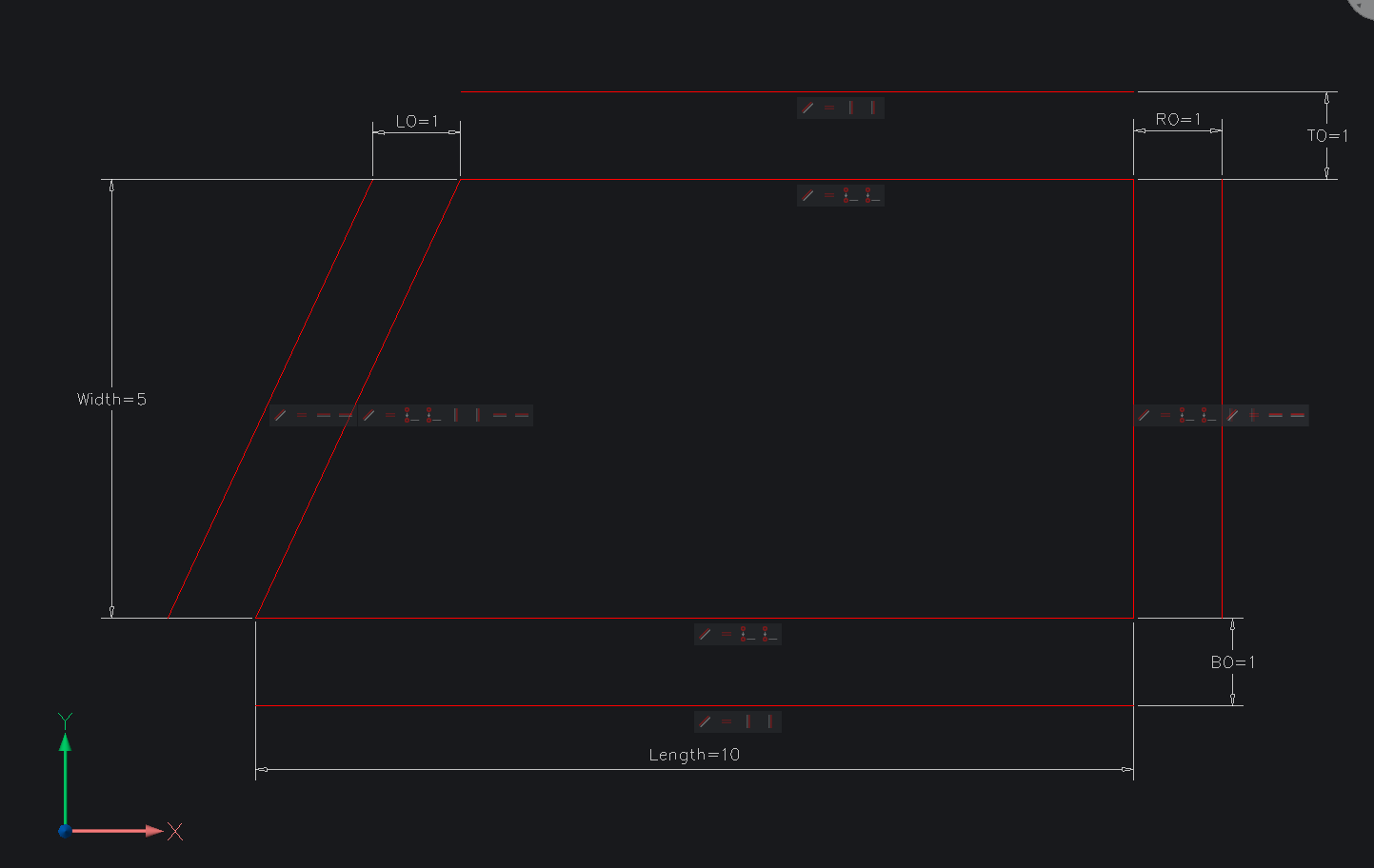
This is after I added a "fix" constraints and a "perpendicular constraint" and a horizontal constraint.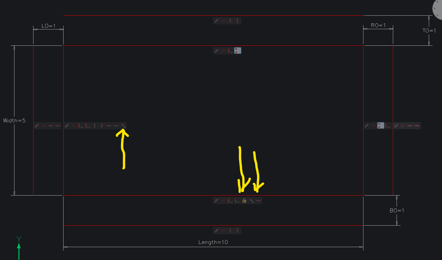
I have also enclosed the file so you can review the changes.
A constraint restricts a degree of freedom if a constrainted object changes in a way you do not expect it does not have enough restrictions on its movement.
I normally start with a line with a "Fix" on it. A fix locks one point of the line in place.
This is the point from where the rest of the drawing moves from, 10 making it predictable in its movement.
Hope this helps.
WIth kind regards
Robert.
0 -
In another post you have a more elaborate unfolded box, have you thought about drawing just lines and plines etc based on info provided ? How many shapes are we talking about bear in mind can add seperate tools to modify a simple say rectang tapers or rounded corners.
0 -
Apologies for being away from this thread so long. My employer cut my hours to 20 per week, and I could not get logged in from home. That is very kind of you to offer me your files David. I will give them a try.David Waight said:Jim,
Funnily enough this is what I make for a living ....
If you just bring them into another drawing using BMINSERT you can alter them to see that they work.
Open the files themselves and you can see how they are constructed.
0 -
Thank you Robert. I will try starting with the fixed constraint. I'm having trouble figuring out how many constraints I need, and which lines they should be associated with. It would be nice if I could click on a constraint and see which lines it is acting upon.Robert said:.......
I normally start with a line with a "Fix" on it. A fix locks one point of the line in place.
This is the point from where the rest of the drawing moves from, 10 making it predictable in its movement.0 -
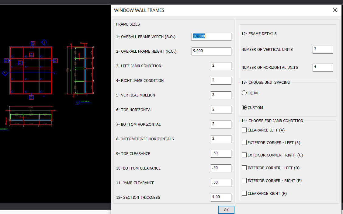
Alan, thank you for your post also. My goal was just to create an automatically adjusting carton template from the template posted by the youtube author. Ideally I could simply input the length, height, and width I want, and the template would grow appropriately. I wasn't thinking about adding options for tapers and rounded corners. How did you get your table for window frames? Is that a feature of BIM? We did not buy the package.ALANH said:
0 -
I have been writing lisp for like 40 years + so its a custom DCL this dcl is based around a library dcl in that it takes 1 line of code and makes the dcl , it uses a list of how many values to get. I have 3 of these library codes Radio Button, getvalue, get toggles.
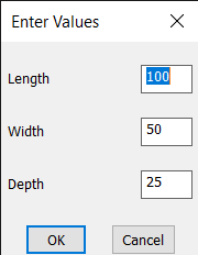
I agree with your comment "would grow appropriately" you can draw a box with options like lid, sides tabs and so on a bit like the DCL for the window frames.
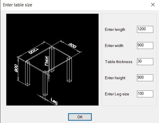
Start with a simple box dwg drawing show it unfolded show the side glue tabs etc. Then can have a think about howto.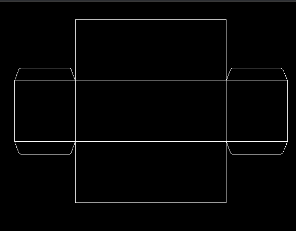
0 -
Alan,ALANH said:..this dcl is based around a library dcl in that it takes 1 line of code and makes the dcl , it uses a list of how many values to get. I have 3 of these library codes Radio Button, getvalue, get toggles.
Thanks for your reply. I'm sure this can be automated. But I've never done any LISP programming. The last programming I did was almost 25 years ago, and was Quick Basic. I don't even know what a DCL is. Visual basic? My problem is now, that this is a personal project, not a directive of management. I had hoped to knock it off in my breaktime at work. But my hours were cut to 20 a week, and I'm dealing with multiple health problems. So I don't have the time to delve into the magic. I will see if I can constrain a simpler object and get that working. I think learning LISP and any other automation are going to have to go on the back burner. Sorry.
0 -
First, DCL stands for "Dialog Control Language"... it is a way to created user interfaces in AutoCAD or BricsCAD. It is like a simple Visual Basic form. ALANH shows one in his message a few up.
Over my career, I have seen many companies using CAD programs at a very basic level. They just don't want to invest the time/money to use it in a more sophisticated way. And sometimes that is a good decision. Other times I think it is short-sighted. They are only looking at how much time it takes to do the project at hand, and they ignore the long-term benefits of investing in more sophisticated use of the CAD program.
For a box, that is an item that is SCREAMING for some automation. The types of folds may be the same, just will different dimensions for various box sizes. So, I would suggest you make a presentation to management, that they provide the funding to create these self-adjusting drawings. It may be by having you personally do the work, or perhaps just pay for a consultant to advise/train you, or pay you to oversee finding others, who know CAD programming better, to do the work.
These kinds of parametric blocks permit you to do in seconds, things that can take a LOT more time. If you are only 20 hours/week now, it could allow you to do the drawings you did in 40 hours, in those 20 hours, or less. Of course, you may want to consider negotiating that they still need to keep you around, because you understand how the CAD programming is working, and to create changes or other versions in the future. So, they should have to take on other roles in the company, or just pay more for your half-time position, while you supplement your work with other jobs.
I haven't seen your drawings. But, it may be that you are making things more complicated than they need to be. Consider that each type of box folding method can be a separate parametric block. Simple stretch commands may be enough, with some of the stretches being controlled by a formula.
-Joe0 -
Joe, This project is a ""government job" - something I wanted to do on my own. My employer's business has been dying a slow death for years. We don't even have a salesman anymore, and I haven't had a payraise in 7 years. I didn't move on because there are few jobs for my skill set in the area. I've struggled with health problems and it is hard for me to commute or attend school.. My eyes are also failing rapidly, and I'm old - 68. .Joe Dunfee said:....So, I would suggest you make a presentation to management, that they provide the funding to create these self-adjusting drawings...... it may be that you are making things more complicated than they need to be...
-Joe
You are right when you say I may be doing things too complicated. (I do all my CAD work manually.), Still I have churned out several thousand drawings since 1999.. I am somewhat aware of what the automation can do... 28 years ago I was working for a company that used Autocad to design checkweigher and other conveyor belt systems for customers. The salesmen would give a checklist of customer requirements to the mechanical engineer, and he would enter them into some sort of program which would not only create a drawing of the complete assembly, but also a pick list for parts. Sometimes it also produced machining instructions for the assemblers. But I wasn't working in that department. I supported the electronics department building prototype circuit boards and systems and testing. I didn't start working in mechanical until I got this job in 1999. I didn't even have a 3D CAD program until 2014. Yes, I've probably had more than enough time to learn how to use LISP, visual basic, etc. Never was a high priority.
I will try and find the time to revisit constraints or some kind of programming. But I have to do it during break time at work.
Thanks to everyone here who tried to help me.
0 -
Just post a dwg that your trying to create then we can comment on how to speed up the process, to give you an idea a project I did replaced about 4 hours of editing a DWG from external software to now 2 minutes. We are talking around a 1000 objects by 4 to be edited. Add blocks, redo linetypes, add direction arrows and so on.
0 -
Thank you for your offer Alan. I honestly don't know how much longer the company's doors will be open, but if you're willing to demonstrate to me how the automation can speed things, up, I'd appreciate that.
The first drawing I've attached is for a lightguide. All our lightguides are rectangular, and must be cut from the center of a piece of lightguide stock using a very special blade on a tablesaw. (The clear stock has a graduated etched pattern on it.) The drawing shows the operator the sequence of sawcuts and rip fence positions (yellow). I have hundreds of lightguide drawings. All that varies is the dimensions of the rectangle, or the the shape of the stock (green). (Some stock has tabs on the corners, and complicates cutting.) In some less common designs, it is possible to take two lightguides from the stock, symmetrically positioned to the left and right of the center, or in some cases, symmetrically positioned above and below center. It would be nice if I could generate a drawing from the input of the stock type, number of lightguides per sheet, and length and width of the lightguides.
The second drawing I attached shows a typical mandrel which is used to hold transformer bobbins for winding on a winding machine. (The end with the set screw clamps to the spindle of the machine.) When the engineers design a transformer using a new bobbin, I have to create a drawing for a new mandrel, and machine one or more pieces. Most of the time the bobbins have a rectangular hole, but sometimes a round one. So we need a mandrel with a rectangular or a round tang. The slot and small holes on the tang hold a piece of formed music wire which applies spring tension to the inside of the bobbin, holding it in position. Generally the only thing that changes from mandrel to mandrel is the diameter and length of a round tang, or the lengths (.850, .700.), width (.354), and thickness (.149) of a flatted tang. On occasion I also change the width and depth of the slot, and the size of the chamfers on edges of a rectangular tang.
Are either of these things candidates for automation?
0


