Display alternate units below primary

Comments
-
I didn't even know it was possible to show two sets of units in a dimension, but after reading your post I played around with it a little. I found that if I enable alternate units by setting "Alt enabled" to "On" in the properties palette, and then double-click on the dimension text to edit it, and then select the first text and press the right arrow key to move over to between the two texts, I can insert the "\X" that makes a dimension text continue on to the next line; and that makes the alternate units text move to the line below.
I can also do it by putting the "\X" in the "Alt prefix" box in the properties panel, but then the first bracket stays on the top line. I couldn't find any way to get rid of the brackets, but maybe you know of a way. It seems like it should be possible.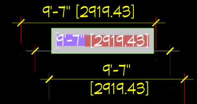
1 -
It is great that you found a workaround for your purpose.
But that sounds like you have to manually have to edit EACH dimension ?
I think this should be better an option for dimension styles.
(I personally do not get the use of dimension styles in Bricscad so far,
concerning existing dimensions ...)
So it would be great if you file a support request.
(AFAIK chances are good that any feature missing from Autocad gets likely implemented)0 -
For all I know, it might be possible to do something with dimension styles. I avoid them as much as possible, and so I know very little about them.Michael Mayer said:.... manually edit EACH dimension? ....
But no, I definitely would not do that editing process for each dimension entity. If I ever had any use for alternate units, and wanted them below the line, I would insert the "\X" at most once in any .dwg file, and probably once for all files. After that, I would copy the doctored entity.
Sometimes I draw dimension entities and then while they're still selected use my reverse Matchprop command to copy the dimension style and other properties from an existing dimension entity. Or draw a bunch of dimension entities and select them all with my QD or QDJ command and then use the reverse Matchprop. But Matchprop doesn't copy the "\X" insertion.
More commonly, I create or paste in one good dimension entity and then copy it around a drawing. To create a string of dimensions, I mirror an existing one around its second extension line and then stretch the new one by its second extension line grip. My entities always stay selected, so it's just a matter of alternately pressing the Space bar and drag-stretching the most recent dimension entity. In the case of alternate text below the line, the "\X" insertion would be in all the copied and mirrored entities.
And my F7 key rotates the selection set 90 degrees (and keeps it selected, of course), and my UU command does that to a duplicate of the selection set. So between those things and the Copy command, I can quickly complete all of a drawing's dimension strings in both directions.
And I have an SF command that sets the scale factor of any dimensions and leaders in the selection set, after first displaying the scale factor of the first entity in the set. So when I go on to a different drawing at a different scale, I just change the scale factor of the first dimension entity in that drawing. That, too, would keep the "\X" insertion.
0 -
P.S. I just discovered that if I select a bunch of dimension entities (QD) and paste
{\A1;<>\X}[]or even just<>\X[]into the Text override box in the Properties panel, then they all display alternate text below the dimension line -- even if they didn't have alternate text enabled before. So that would be another way to avoid manually editing each dimension entity.
I don't know what the{\A1;}means, but after playing around a little I think the two brackets are the key to having alternate text enabled.<>just means the actual dimension, and so<>\X[]apparently means the actual dimension plus the alternate units below the dimension line. So it's probably not possible to get rid of the brackets around the alternate text.0 -
This is pretty good, and I'm applying it to my drawing right now. Thanks for figuring it out and replying.Anthony Apostolaros said:P.S. I just discovered that if I select a bunch of dimension entities (QD) and paste
{\A1;<>\X}[]or even just<>\X[]into the Text override box in the Properties panel, then they all display alternate text below the dimension line -- even if they didn't have alternate text enabled before. So that would be another way to avoid manually editing each dimension entity.
I don't know what the{\A1;}means, but after playing around a little I think the two brackets are the key to having alternate text enabled.<>just means the actual dimension, and so<>\X[]apparently means the actual dimension plus the alternate units below the dimension line. So it's probably not possible to get rid of the brackets around the alternate text.0 -
I don't get it either, after 34 years of using Autocad and Bricscad. I only use dimension styles to assign properties to newly-created dimensions. After that, each dimension entity is on its own, and I alter properties of one dimension entity or of a selection set using the Properties panel and my various custom commands.Michael Mayer said:.... (I personally do not get the use of dimension styles in Bricscad so far, concerning existing dimensions ...)
0 -
I submitted a request for this feature0
-
Pity "Styles" are just a template when creating things.Anthony Apostolaros said:I only use dimension styles to assign properties to newly-created dimensions.
Maybe I just have wrong expectations.
For me Styles (Dimension Styles, Line Styles, Hatch Styles, Wall Styles, ...) are more to organize.
- stylize unstyled objects
- replace Styles of objects
- adapt Styles to force stylized child Objects to follow changes
But such kind of Styles are called "Compositions" in Bricscad BIM.
I assume all that 2D bevahior I struggle with,
(Paperspace and Viewport scales, dimension styles, annotations, scrolling in selected Viewports)
was just copied over from the last 200 years
of Autocad development into Bricscad for Autocad compatibility sake (?)0 -
I'm not saying dimension styles can't be used for other things. Maybe they can be used to control existing dimensions. But if so, the process is too confusing for me, and I found other ways that seemed easier.0
-
Just a comment had a play with VL code
Original (vlax-get obj 'Textoverride) TextOverride = "\\A1;<>\\X[]"
(vlax-put obj 'Textoverride "<>\\X62.83") no brackets.
So if can work out other value like * 0.3048, * 25.4 edit the text string.
Looking further
; AltUnitsFormat = 2
; AltUnitsPrecision = 2
; AltUnitsScale = 25.40 -
I played around with it and found a slight edit so they don't have to be edited individually to get the square brackets to stay on one line, rather than putting \X in the Alt-prefix put it in the Primary suffix after your chosen unit (i.e. I had my primary suffix set as "m" for meters, my primary suffix has now become "m\X") Hope this helps someone
0

