Wall Extrude... no top or bottom faces!?

I am starting to play with taking 2D plans to 3D and just watched one of your online tutorials.
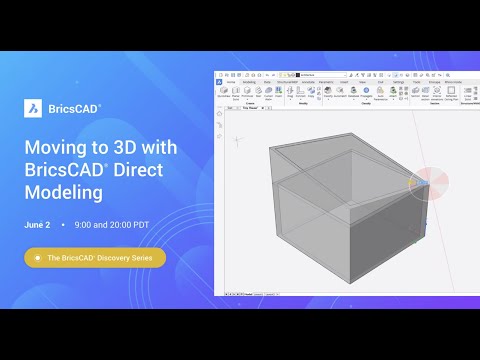
When I extrude wall lines, I do NOT get top and bottom faces. All that is generated are the vertical side faces?
When I extrude wall lines, I do NOT get top and bottom faces. All that is generated are the vertical side faces?
0
Comments
-
So it is all Lines ?Just_Me said:
When I extrude wall lines, I do NOT get top and bottom faces. All that is generated are the vertical side faces?
If you extrude a (1D) Line, by definition this will end up in a vertical but still (2D) Rectangle.
If you your extruded result should be a true volume, you need to extrude a 2D "face"
like e.g. a rectangle.
So you need to create a closed polyline from your lines - for each wall or group of connected
walls, if applicable.
(But maybe drawing over with "Quick Wall" tool may be easier)
0 -
Instead of selecting the lines to extrude, you can adjust SELECTIONMODE to detect Regions - the 2D space enclosed by a closed loop of lines, circles, polylines, whatever. Select and extrude those, you get a solid.
However, to select the Region when you click on it, the box symbol whatever it's called which surrounds your mouse point, has to fit entirely within (not touching) the lines etc which surround the Region. At the same time you have to be zoomed out enough, that the whole region is visible on screen. Similar to selecting areas for Hatching.
That can make it refuse to extrude the walls of an entire building in one go, by selecting the Region that is the wall thickness - you have to be zoomed in enough to get the selector box between the lines, but need to zoom out enough to see the whole.
Gave me (and Support) much grief, until the simple explanation was spotted! Make the selector box much smaller in Settings and/or break the whole extensive wall plan into smaller sections.0 -
For context i am trying to replicate this:
 https://youtu.be/oU8OkO4OOgY?t=971
I thought I had set it to detect regions as per this video but perhaps not correctly as it does sould like a possible cause.0 -
I even just tried to extrude a two point rectangle at that does't create top and bottom faces, just a vertical tube once again so something isn't right!0 -
I also just created a new drawing using the modelling set up, created another 2 point rectangle, extruded it and got a tube again so it must be a bug or a global setting that is amiss.0
-
I tried that.
Draw a Rectangle.
Hover over it, QUAD > Model Tab > ... there are 2 Extrude options
- Surface Extrude (Your result missing top and bottom faces)
- Solid Extrude (creates a solid Cube)
I use Bricscad BIM0 -
I initially didn't suggest this,Tom Foster said:Instead of selecting the lines to extrude, you can adjust SELECTIONMODE to detect Regions - the 2D space enclosed by a closed loop of lines, circles, polylines, whatever. Select and extrude those, you get a solid.
as I thought it would only work with 3D geometry.
But I tried and it works great !
So if the Sketch from Lines only, already exists,
I think using the Boundary Mode should work well.
0 -
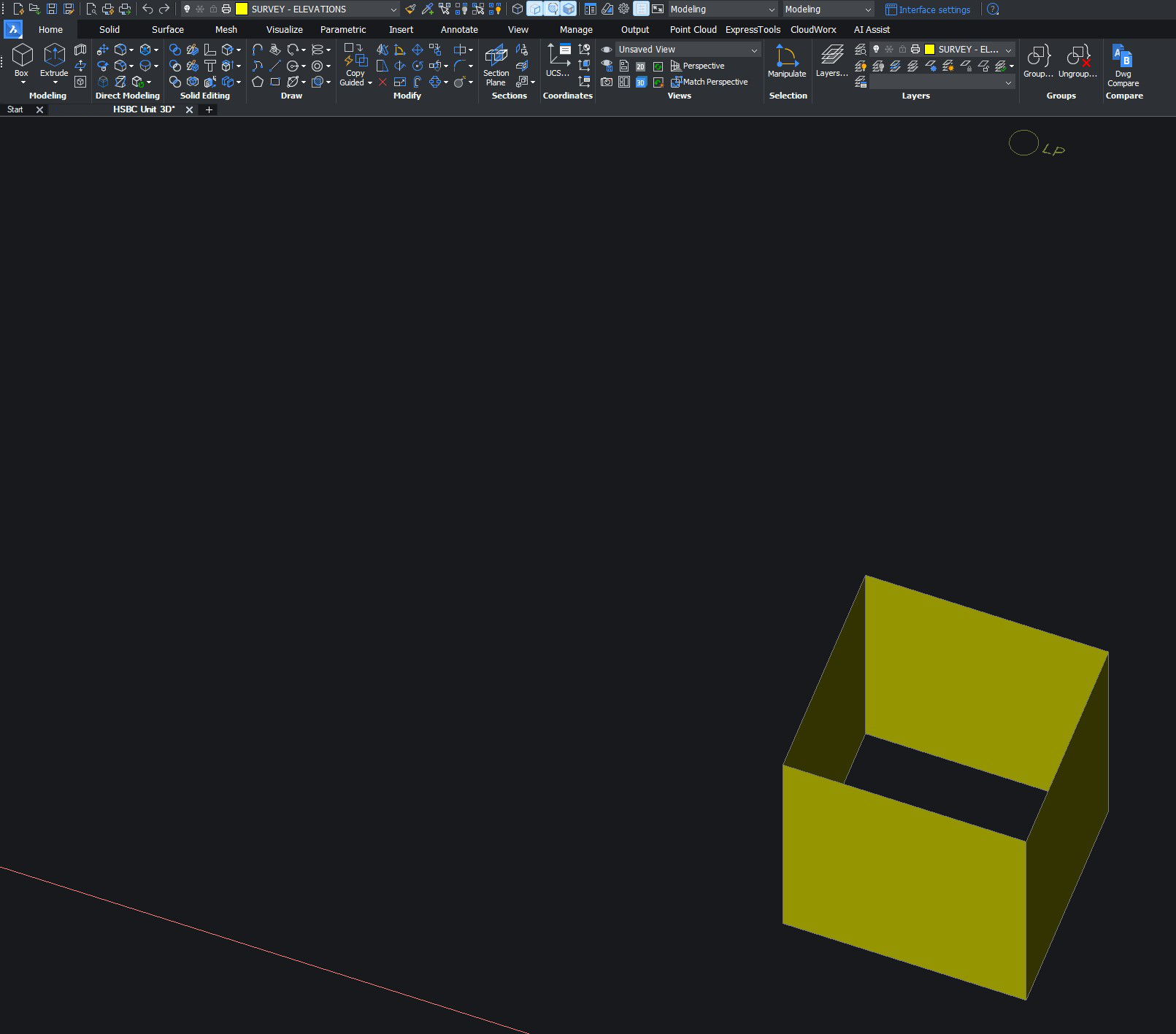
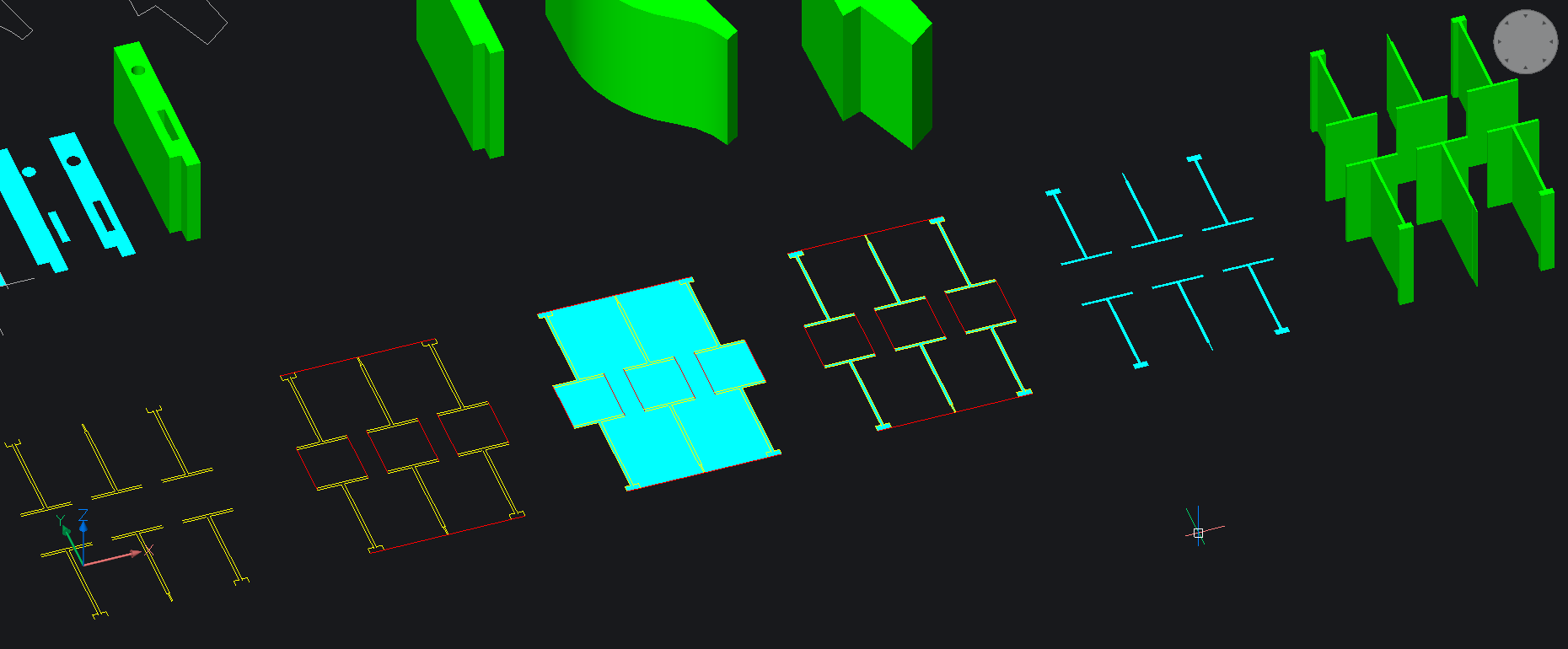
If you have areas enclosed by 2D linework, you can always create regions using the command REGION (cyan)
Then you can create 3d SOLIDS (green) by extruding the regions...
Lines have not to touch perfectly, they can arbitrarily cross and you can have enclosing gaps !
You just select the regions that should be subtracted from the main region(s) using the SUBTRACT command
In this way you can always produce a complicated wall...and you can select many closed areas simultaneously and create many walls in one step
See following screenshot....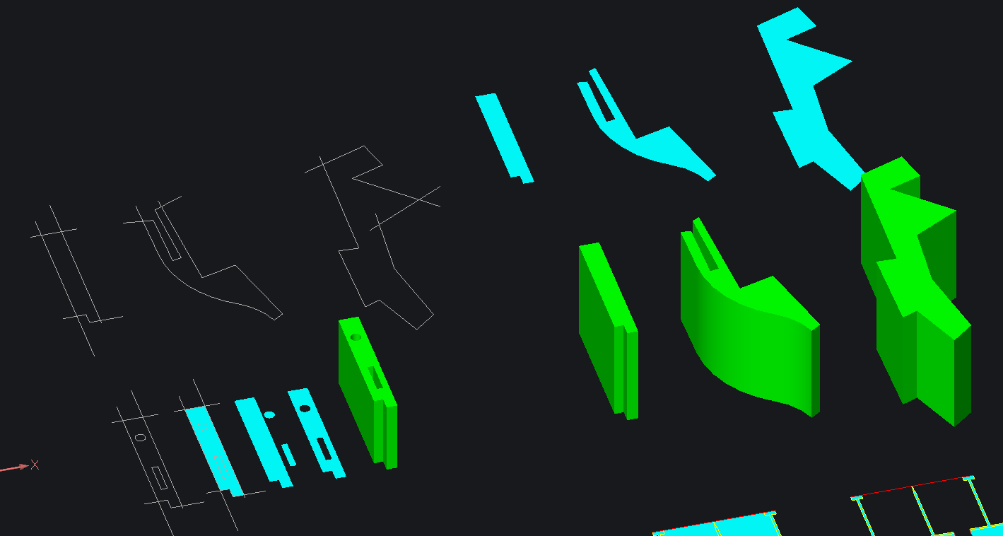
If the areas are not enclosed (yellow) then you can draw appropriate lines (red) closing the areas, create regions (cyan) by selecting all linework, erase unwanted regions an finally create 3D solids (green) by extruding them. I attach the dwg .......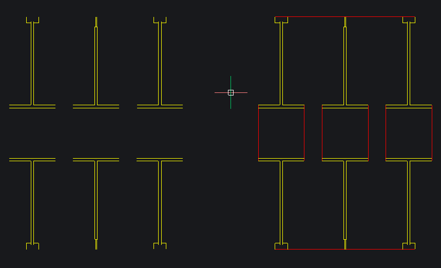
0 -
Thanks for all the help but I am coming to the conclusion that BricsCAD is a bit crap in this area. You are indeed correct that there are two types of Extrude which I can perform on a 2-point rectangle but in the case of my attempt to pull a 3D plan from a 2D one, it is simply refusing to offer solid extrude. It will happily offer surface extrude all day on anything. Attempting to turn parts of wall to a region first also results in some of it being deleted.
It's pretty useless really. The lines in question are totally flat and there are no gaps. The video I pointed to earlier on is clearly making out you can easily do this which is proving to not be the case at all. I should point out I have used multiple CAD platforms since the 90s so if I can't find ow to make this work easily it's not easy.0 -
....well would you know if, did absolutely nothing different and it decided to work. Having now played about it seems that it is way to sensitive to viewing angle etc. You can try to solid extrude the same lines several times from multiple distance and viewpoints and only half the time does it offer up a region highlight and allow a solid extrude.
Verdict: Needs work!0 -
I am usually in an Isometric View only as I do 3D only and need to have control in all 3 axes.
That is where I just tested drawing 2 overlapping Rectangles and noticing that
"Enable Boundary Detection" works for 2D elements too.
So if I would get such a 2D drawing source from external,
I would run Optimize to avoid any possible inaccuracies like gaps, overlappings, ...
then I would draw over with Quick Draw.
I think for me that would be faster than extruding multiple parts of Walls.
Meanwhile (V23 ?) since in Bricscad BIM we have that great top plan mode with Stories,
I do most drawing over underlays in 2D top plan view mode.
(Walls, Windows, Doors, ....)
But from time to time just rotate my Story top plan View to an ISO to get Z control
but still being able to overall draw reliably on Story's Z height only.0 -
A 2-point rectangle is just 4 lines, so will correctly extrude as a tube - nothing to do with Surface mode vs Solid mode. You can choose - either extrude the lines to a tube, or the enclosed Region to a Solid.0
-
This is what I call 2 1/2 D yes not finished missing some doors etc. Just a dummy image.
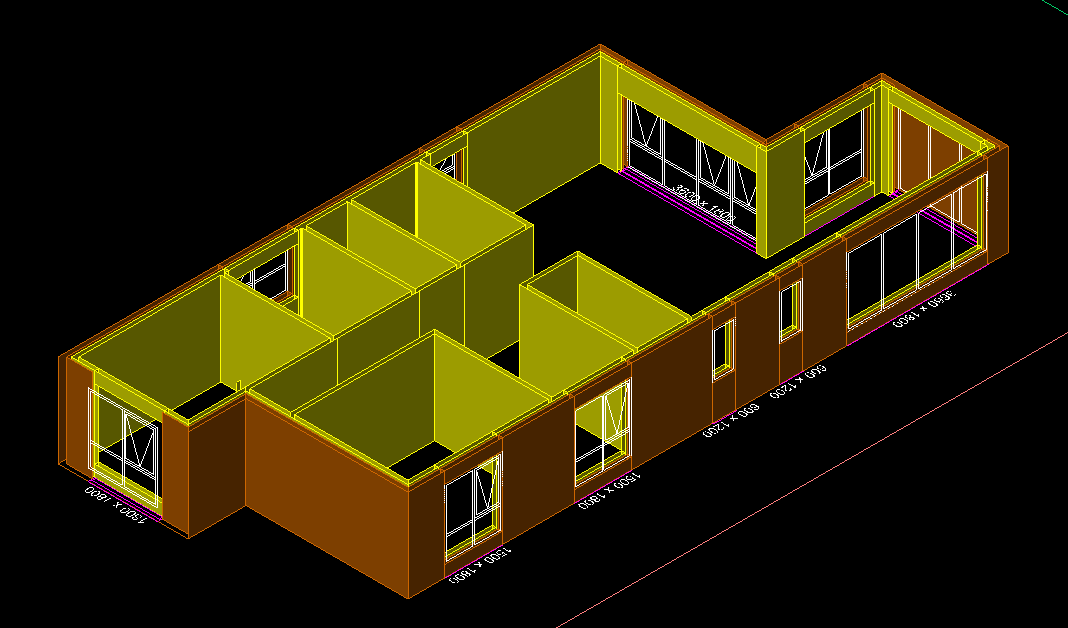
When it comes to the roof used Pface. Which makes like a sheet of roof panels.
Part of a simple house package, 130 lisps.
0 -
Could that be because, as I said: "you have to be zoomed in enough to get the selector box between the lines, but need to zoom out enough to see the whole". That did make it tricky, but not a problem if you understand what you have to do.Just_Me said:You can try to solid extrude the same lines several times from multiple distance and viewpoints and only half the time does it offer up a region highlight and allow a solid extrude.
0


