'Family of Parts' (Various Sizes/Angles) Creation via 2D Parameters Possible?

Can 2D parametric tools streamline a family of parts of the following profiles?
I have been tasked with creating several 2D profiles of items formed in sheet metal.
For each item 2D profile, there are six (6) variations per drawing now tabulated.
There are two (2) angles ( A and B ) and two (2) lengths ( C and D ) that vary per each item profile defined by roughly a dozen total dimensions.
I created the first set of six (6) variations 'manually' per the (4) varying tabulated dimensions (angles and lengths).
I am aware of the possibility of generating a 'family of parts' or parametric 3D but have not yet explored 2D parametric tools in BricsCAD Lite.
Your thoughts are appreciated!
A BricsCAD BIM upgrade happens very soon.
Would the 3D-based BIM parametric functionality be better suited to my effort?
Comments
-
I am not very experienced with 2D/3D constraints as my brain is doing a bit hard with this.
(Otherwise I would already have build my own custom insertion objects for Doors and Windows)
But I do not think that Bricscad BIM would help much.
I rather think you should take a look at Bricscad Mechanical.
This is where you can use "features" like holes or fillets that you can parametrically adjust
and move around. This happens mostly in 3D and it has a full Sheet Metal tool set inside.
But that may be overkill, depending on how offen you will need that.
So I think, if you only need 2D it is worth to check the options in Bricscad Lite.
(And search for related videos in Brickscad's YouTube channel)
Not sure if Lite also contains Parametrize command which does fully constrain a selection
of items automatically and if it only works with Solids, not 2D (?)
But there should be the 2D and maybe even 3D Constrains.
So just a few thoughts.
I hope someone more experienced with that matter will chime in.0 -
Hi Michael,
I thank you for your time and thoughts. Yes, Lite allows auto-constraining that I used.
The double-line (representing a sheet metal thickness), closed polyline is complicating the issue.
(Immediate "ah-ha" moment just occurred: Test using a single-line profile version first!!!)
OVERKILL
The amazing Auto-constrain generated a host of constraints - too many for my purposes - (four variations are desired).
TERMS
Part of my issue is differentiating between and choosing which of the less obvious constraints - collinear versus parallel - for example.
GOOD STUFF
The animation of the two angular constraints are straightforward and easy to interpret.
NOT SO GOOD STUFF
Many other auto-assigned constraints show no visible movement while the application crunches though what is supposedly an animation - albeit an invisible one.
There are many geometric relationships to consider and test here!
That single-line profile flavor may shed light on what to assign to the double-line profile.
0 -
@Clint2U
yes,definitely.
watch this video from bricscad.
it is also show how to link a drawing to an excel table to make many parts from a basic component.
0 -
Thanks "aridzv" !aridzv said:@Clint2U
yes,definitely.
watch this video from bricscad.
it is also show how to link a drawing to an excel table to make many parts from a basic component.
I am using Lite at the moment.
Plans are to upgrade to BIM (but not Mechanical.)
Does BIM include this same functionality?0 -
As said, the manual constraining's abstraction and logic is a bit hard for me.
And I watched videos about auto constrain.
I think it is great but to get that total constraining back into a manageable
constrained system seems still like a lot of work.
Before auto constrain I saw videos on how to create own Windows by manual
constraining. That would cost me days for even such relatively simple part ....
But maybe with auto constrain it would be manageable to dump it down to
your parameters of interest ....
But it is still not that intuitive from an architectural view.
I assume BIM contains all Constrain Features as Mechanical.
And we have that Mechanical Browser Palette that we need to control our
constraint. Not sure where the BIM limit for Mechanical Features exactly starts.
Maybe a Support Request would bring some clarity.
0 -
Thanks Michael! I have submitted just such a request. I will update you via this thread. It may be several days.Michael Mayer said:As said, the manual constraining's abstraction and logic is a bit hard for me.
And I watched videos about auto constrain.
I think it is great but to get that total constraining back into a manageable
constrained system seems still like a lot of work.
Before auto constrain I saw videos on how to create own Windows by manual
constraining. That would cost me days for even such relatively simple part ....
But maybe with auto constrain it would be manageable to dump it down to
your parameters of interest ....
But it is still not that intuitive from an architectural view.
I assume BIM contains all Constrain Features as Mechanical.
And we have that Mechanical Browser Palette that we need to control our
constraint. Not sure where the BIM limit for Mechanical Features exactly starts.
Maybe a Support Request would bring some clarity.0 -
The other way of approaching this is draw objects from 1st principles, you still enter all the relevant details about lengths and angles, last question is pick point. Lisp can produce extremely complex objects very fast. Could make a block out of final result. So can be copied etc.
Hopefully this video works.
0 -
The lisp example is impresive indeed,
but it will requiere the user to input a lot of information for each component.
the componnet link to a table will indeed requiere the user to create the base componnent,
a task that can be tedious, at least with the first few componnents,
but to work with them it will be much easier - see attached screenshot:
on the top is the table and on the lower part I marked the dropdown list that the user choose from.
The task of building these components can indeed be exhausting and you need to develop skill in doing so,
But once you acquire that skill I think this approach is better.
aridzv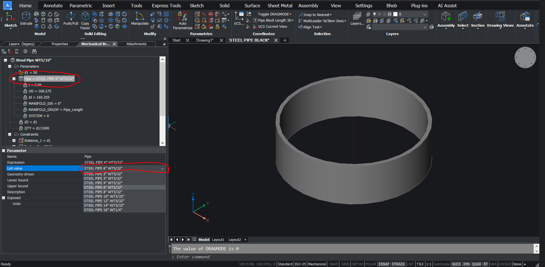
0 -
There is not a problem in having the "drop down" pop up in a dcl so you can choose, look again at the video the window options are read from the dynamic block not hard coded, the lisp makes the dcl to suit on the fly.
0 -
I am catching up on some very substantive and useful ideas. Wow! The issue in my situation is an apparent limitation in BricsCAD Lite parametric functionality as far as user-defined parameters are concerned.
Example:
A U-shape profile is 4.oo inches on all three sides as measured from the outside edges with 90-degree corners and constructed with a 0.0188-inch wall thickness as a closed 2D polyline:
Given:
The right wall of the U-shape profile will not change either in angle or length.
Question (and the objective of this exercise):
How do I assign constraints to both the left and bottom wall lengths and the angles at each corner of the profile such that when one or more of these angles or dimensions change, the others change as well? Again, the right wall angle and length does not change.
Thanks for any and all input related to this issue in BricsCAD Lite.
(A future upgrade to BIM is anticipated.)
Clint0 -
Hi Clint,
We don't all work in your discipline, so could you upload a drawing so we can all see what you are trying to achieve?
Although we don't create the same products as you, similar rules will apply when constraining your model so we should be able to help.0 -
Thanks David! The two angles and two lengths will change with the right vertical leg that is the attachment point for this, a gutter profile, on a vertical eave) This right vertical leg changes only in length. In other words, this exercise is to generate six gutter profiles based on six different roof slopes that are now only tabulated on a drawing.
P.S.: There are five more styles of six profiles each yet to define as well.0 -
Clint,
I had a quick play and added some constraints to your drawing (the copied one on the right).
I didn't add user-defined constraints, just renamed constraints as I added them.
They are a bit all over the place in the Parameters Manager list (Bricscad presently doesn't have the ability to sort the constraints after you create them).
I also added some dimensions (with the constraint names in brackets) to the elements to move so you can see they are changing (don't double-click these to change their values, they are just ordinary dimensions).
With the Parameters Manager Palette open change the values of the named ones that are variable and see if the model changes as required.
I ignored the Table and also all the Leaders you had turned off as I wanted to see if I could make the model do what you wanted.
Hopefully, I have understood your requirement correctly.0 -
David,
I thank you.
Your interpretation was spot on and your example works as desired.
My first reaction: There are several more constraints needed than I anticipated!
With the values as five place decimals exposed, it appears I need to make a 'cleaner' model. For instance, The constraint d10 = 0.999823 inch value is showing instead of the desired 1.000000 inch value. I just know I had measured it to the exact desired value/accuracy but apparently not!
Due to the pushed schedule lately, establishing the relationship among the constraints was a bit trickier in my mind. Time will be required to inspect each constraint in order to produce future models.
This model serves as a prototype on how constraints can be used to best advantage and your time and effort makes application of constraints crystal clear - a confidence booster for sure!0 -
Sometimes for simple shapes like this just make it as a pline, you know what the shape is to look like so you work out all the points making the pline. Forget co-ordinates, just ask for a relative point, say top left then work out all the points.
I wrote multi getvals.lsp for just this task its 1 program that creates a dcl for input you can have like 20 inputs, the inputs have a default value which you can change. You can use it in any code. Is the zig zag side left always that shape ? Does it get longer in relation to your 0,0 The only change is width, height and the angles ?
An easy task. Yes have to work out points, but that is what Polar function is for.
Watch this space.
0 -
Alan,
I appreciate you sharing your thoughts and your methods along with the dialog box. I couldn't agree more with all of them.
Mastery of a couple of programming languages, including Visual LISP, is a renewed goal as I enter into a new phase of my work life where I can make direct application after much time away.
The object of this specific exercise is to create 2D profiles for use in a 3D application's that includes text-based support files only. This particular code includes X,Y coordinates that define the 2D profile of a particular piece of building sheet metal trim.
Therefore, a single polyline cannot be utilized in this case. The double-line represents the thickness of the material that has at least three variations.
Your contributions are highly valued in this thread.
I look forward to further ideas on this topic and participating in future discussions with you on this forum in general.0 -
The thickness can be added, same with the fold bend rules. You can draw plines, offset them and add round end caps.
these are plines.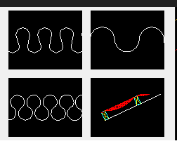
0 -
This is a very interesting point. I would like to explore how this can be applied to thin-walled (0.0188 inch) dual line profiles. Let know if you have the interest to review an uploaded CAD file that may clarify my task.0
-
Do you really need to draw 2 lines to imply 0.0188 inch thick. Could do 1 pline 0.0188 thick. That is like 1/32" Dont any plumber that good.
Given that the sample is a roof gutter why bother with more than a single line. The gutter manufacturer will know how to make it to your size taking into account bends. So your talking a 6" gutter to outside a dim more relevant than inside dim, it will overide any 1/16" difference in size. Had to think about it as I work metric so 150 not 147.0 -
I understand. In normal circumstances, a single PLINE would suffice.
In our VERY unique circumstances, I MUST draw the PLINE as a double line define each profile.
I use a CAD LISP routine that harvests the 2D (X,Y) PLINE vertex coordinates, creates a TXT file, and populates the TXT file with these coordinates.
I paste this list of coordinates representing both the sheet metal thickness and profile into a 3D design application's text-based support file.
This application extrudes the profile into a 3D piece of sheet metal trim of which there are many types and variations.
Therefore, I need a double-line PLINE profile.0


