A hole in a TIN

Need to cut out the bit of TIN surface within the building's footprint. How to?
I know the TIN can't have a hole in it, so should it be a vertical-sided pit in the TIN, its bottom well below founds? Can this be achieved by SUBTRACTing, or by extruding a polyline downward? Any hints?
Comments
-
Hi Tom,
The trick is to imagine having TIN with a hole that can be transformed to 2 adjacent TIN's encompassing the hole. The starting point is a TIN and a polyline representing the 2D footprint of your building.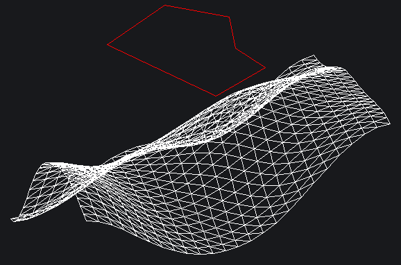
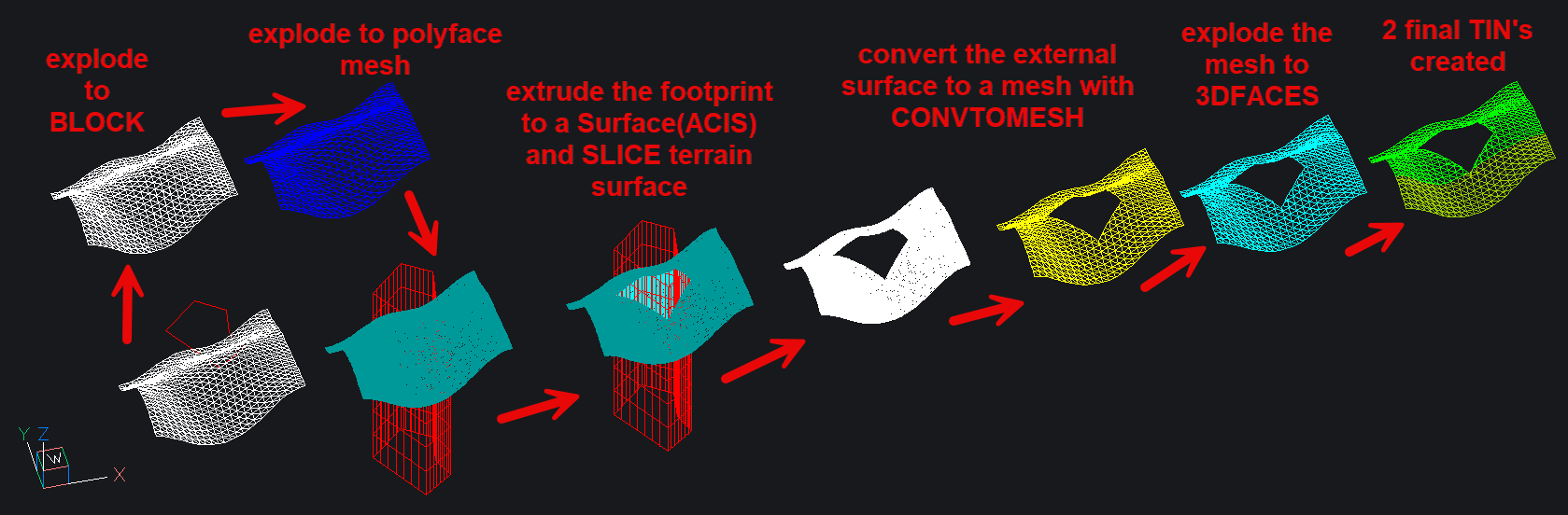
The steps:
1. Explode the original TIN twice to get a Surface (ACIS).
2. convert the polyface mesh to surface ACIS with CONVTOSURF
3. Extrude the original footprint to a surface(ACIS).
4. Slice the terrain Surface by the footprint extruded surface using SLICE option Surface
5. Convert the external surface to a mesh with CONVTOMESH
6. Explode the mesh to 3DFACEs
7. Create 2 TIN's using in Plan View Window-Selection twice, so that no window contains the hole completely
That's it ! you have now 2 tins representing exactly the original TIN with a hole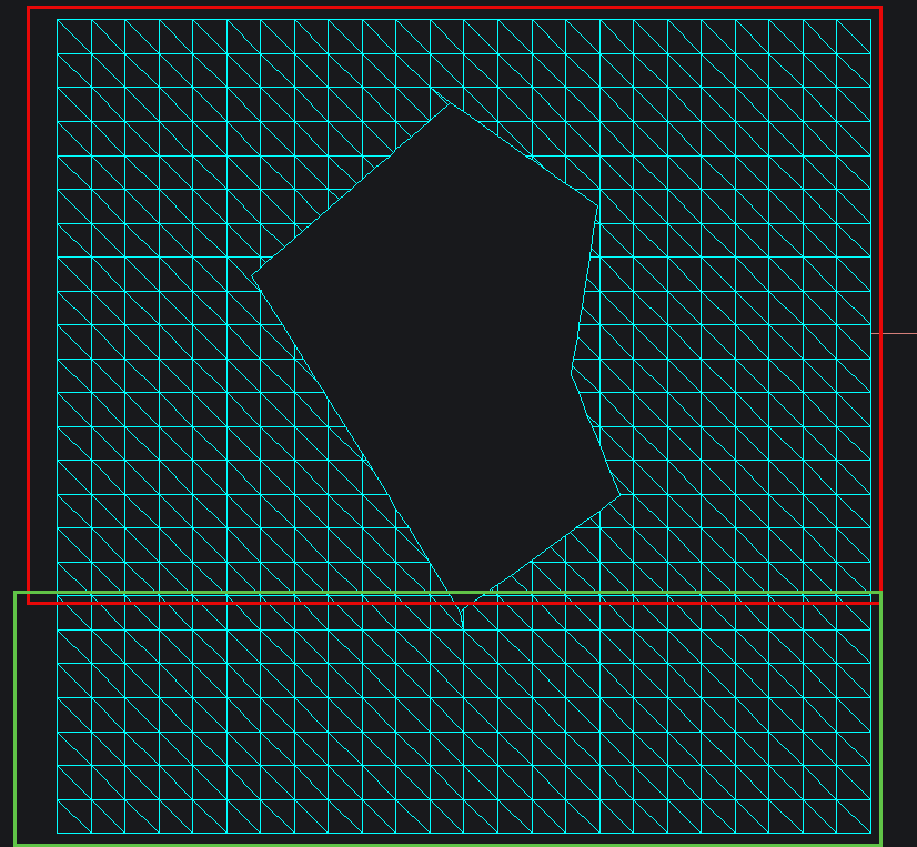 0
0 -
Blimey! I suppose that coiuld become quick and efficient.
How about just making a vertical sided pit (with flat bottom)?
0 -
This is much simpler if you use a BricsCAD TIN surface instead.
Once you've created the TIN surface you can simply use TINEDIT to add Boundaries to create holes in your TIN.
The neat thing about this, is that can be dynamically updated. Modifying the boundary will automatically update the tin surface. You can even use grading objects as a boundary definition, which is useful in the case of defining a platform to place a building on.
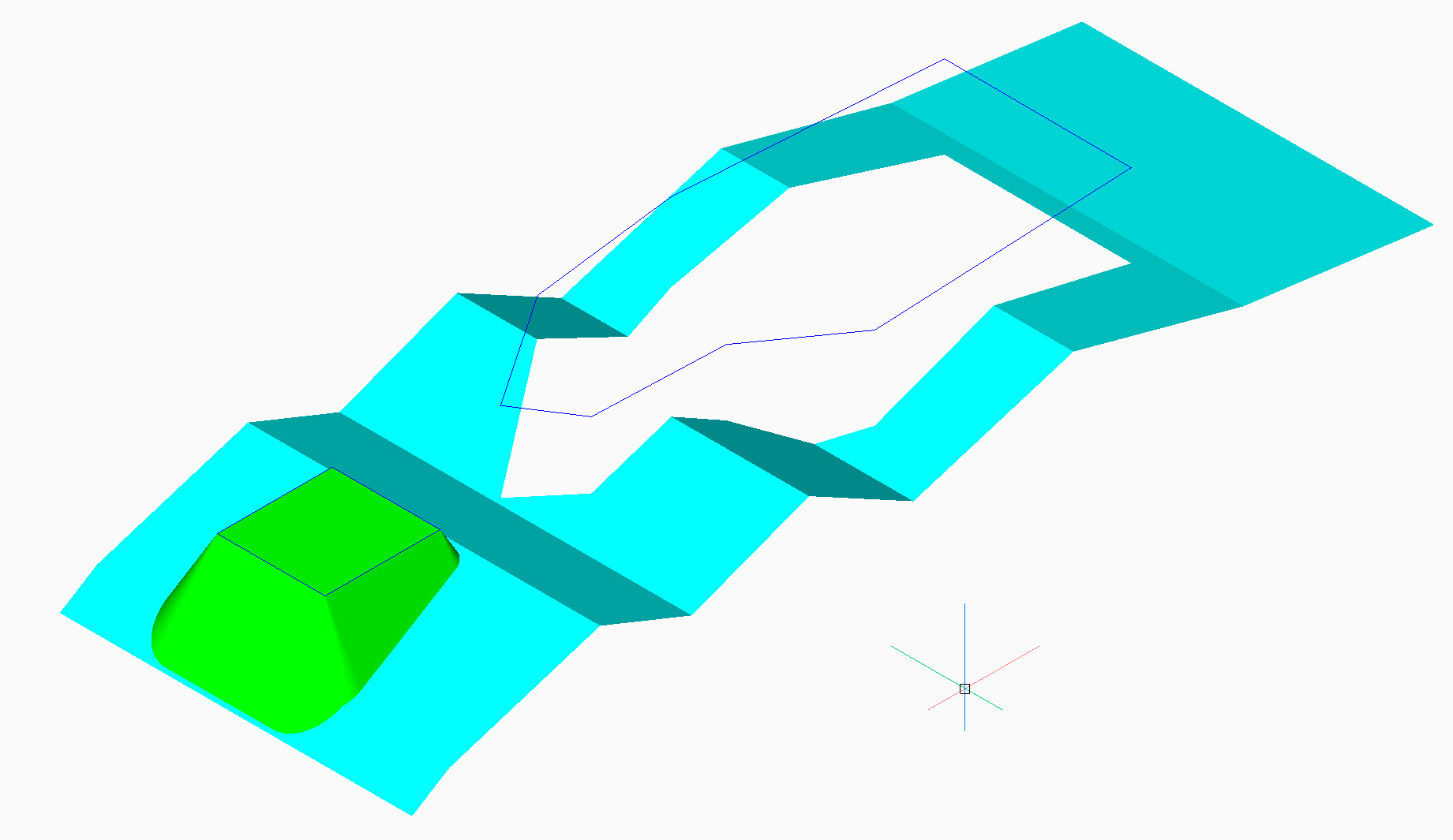
The attached file illustrates these options.
Jason Bourhill
CAD Concepts Ltd
1 -
Yes this is definitely the way to go !
I also tried the "Add boundaries" option of the TINEDIT command but i selected the clip option and not the hide option, which in effect hides the triangles inside the boundary polygon but if you export and import again the tin surface, the 3d faces (triangles) are still there…0 -
You can use the TINMERGE command to combine surface edits into a single new surface

When exporting your best to chose a format the retains all the details of the TIN surface, such as LANDXMLEXPORT
Using LANDXMLIMPORT will rebuild the surface and include any modifications, such as holes

If you export just as 3DFaces, then you would need to include any boundaries to allow you to recreate the surface again.
Jason Bourhill
CAD Concepts Ltd
0 -
Thanks guys. This is a Bricscad TIN I'm talking about. Looks much easier than I thought - will get back to it shortly.
0 -
Also, you can delete manually the triangles of the TIN where you don't want them.
0


