Tips Needed on Setting 2D Constraints with a Sample Family of Parts

I am studying the BricsCAD Help section covering Parametric Constraints and am having difficulty applying what I read. Usually, an extra tip or insight from experienced users provide the answer.
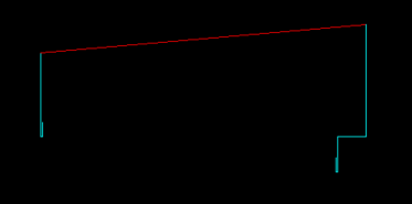
Referencing the attached drawing, I have included the following:
1.) At top: A modest reference dimension table and dimensioned part
2.) At bottom: An attempt to apply constraints to the geometry.
You may notice that the two dimensions, "A" and "B", vary among the (15) fifteen different part variations identified as CP1 through CP15.
My question is:
Which constraints, both geometric and dimensional, can achieve the desired results?
Comments
-
I dont understand you can only change 1 dimension as its controlled by internal angles. Changing A will give you a new B, Hopefully as you have listed.
Have you thought about just draw the pline based on the information of all the dims? Just work on 3 parts then join the parts into 1 pline. Not hard at all.
Start with say lower left pick point. Does the 4 change ? Does it move up or down as you change "A".
You have my email can talk there.
0 -
I will email you, Alan.
0 -
@Clint2U I don't usually use Design Tables, so I may have the wrong end of the stick as to what you are trying to achieve.
I copied your shape and changed some of the constraints to what I perceived you were trying to make work.
The one on the right is the one I created, and I made a Design Table of the names and sizes of A.
I only used A as I couldn't see how you could make the angles work, as the length determines the angles and distance at the top, if either of the two ends don't change in height.
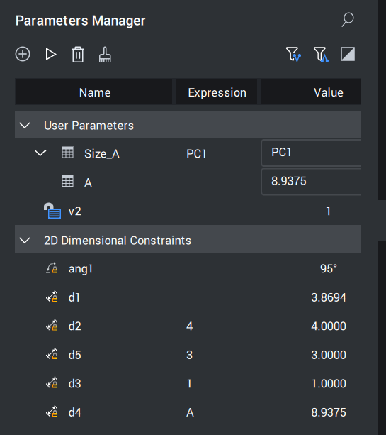
If you look in the Parameters Manager or the Mechanical Browser, you will see a Table called Size_A.
This has a list of all the codes with their sizes, so if you choose one, the distance of A will change.
I work in metric, so I had to turn all your measurements into decimal inches so I could work with them.
You will need to rename the text file to .CSV, as the forum doesn't allow .CSV files to be attached.
Apologies if this isn't what you were wanting, but at least I learnt something trying to create it :-)
 0
0 -
This is a great example, David!!! Your hard work and interest are sincerely appreciated.
The issue: The 85-degree angle as well as the 95-degee angle both remain CONSTANT. The geometry changes horizontally only based on Lengths "A" & "B".
Please refer to the attached file containing (15) fifteen versions of the PC series based on Visibility State version that proved inefficient as the user must erase the unused geometry and the unused Visibility States as well.
P.S.: I have up to BricsCAD BIM - now, in the pre-engineered metal building (PEMB) industry with a mechanical design background - so I may ask for an upgrade to Ultimate (including BricsCAD Mechanical) for exploded 3D isometric building component views alone!
Regards,
Clint
0 -
@Clint2U I have no idea what any of what your P.S. said as I'm not in your industry :-)
I am slightly confused because as far as my (limited) knowledge of geometry is concerned, you can't constrain A and B, as B is a result of A's length.
With the two angles, again, I can't see how these can remain constant without either of the verticals that B is connected to changing in height.
I've attached a file (sorry it's metric), which I took from your suppressed items and scaled to work with, and the angles of B aren't constant.
I profess to knowing nothing about visibility states, as I don't come from an AutoCAD background (again, I've learned something else today).
0 -
Thanks! I am inclined to agree with you. I did not create this detail and must review it further as a lesson in geometry/trigonometry.
Any change in the horizontal distance of the 'driving' dimension "A" will change the base 95-degree angle to a different angle at the least along with changing the resulting 'driven' length "B".
The Visibility States feature is native to both BricsCAD as a parameter as well as AutoCAD as a dynamic block option.
P.S. to the P.S.: 😁I shifted to this manufactured building industry recently as a majority (75%) of my past experience is in mechanical design.
0 -
Now that we know
"Any change in the horizontal distance of the 'driving' dimension "A" will change the base 95-degree angle"
Then changing "A" only can be achieved and for me just draw the shape no need for a block.
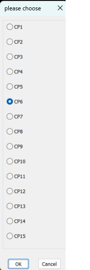
I work metric also so will try to get to work imperial. Fifteen choices can be done as a pick DCL.
Watch this space.
0 -
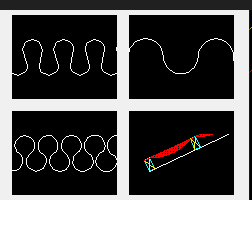
Ok have a look at this the next step would be to do dims. You have all the point numbers in an order so can do dims.
As you may have more shapes i would use a menu with say image selection for the shape rather than say a name only, "CP shape". You can then have only 1 lisp but it would have a defun for each shape. Look at this image as an example.
The other thing I could have done a dcl that had say A B C D E F variables so they would match the dims sizes and change shape.
0 -
AlanH,
These are wonderful learning examples that I intend to eventually gain fluency in composing programs similar to them. I am indebted to you for freely sharing your knowledge. Your skill is not lost on me!
I will message you on the latest news.
From an experienced building designer, I just learned that the angles remain constant as the "A" dimension changes resulting in a change to the "B" dimension. So, it appears all I must do is constrain both angles and effectively perform a horizontally linear adjustment.
Yours,
Clint
0

