HELP: Superelevated Road Curve Method, Right or Wrong?
Hello, Firstly I would like to thank for the previous question that you guys answered. I didn't had the time to reply on that and I do apologize.
Moving on, I would like to ask if the following way I've done is the right manner of drawing out the Road at a curve.
Steps I've taken:
1) Draw the TIN based on the Original Ground Level (O.G.L).
2) Place the road and earthlevel plan-view drawings together.
3) Used Alignment by Pi on the Road's centre lines.
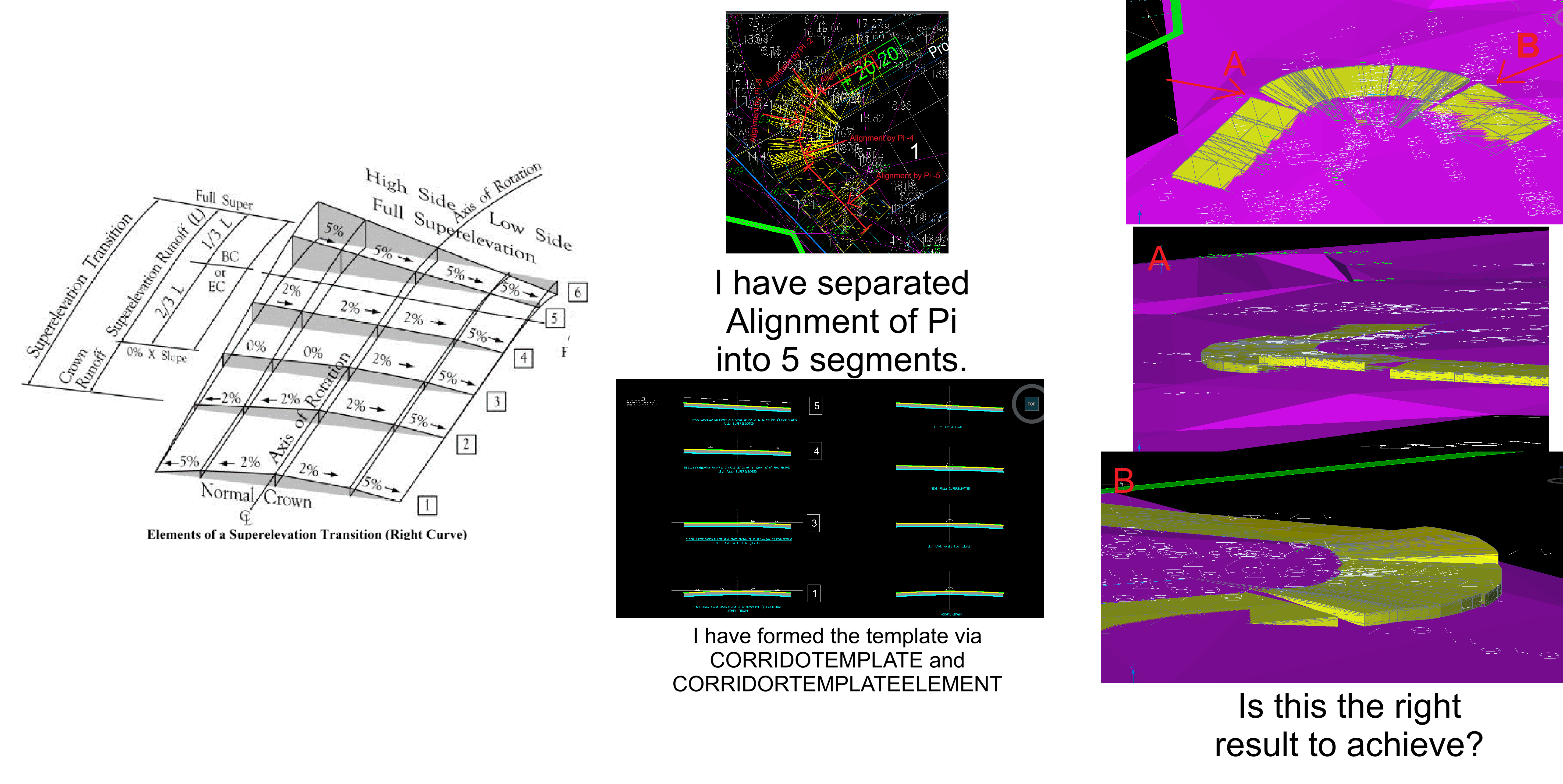
4) Split into 5 segments of Alignment of Pi.
5) Draw the elements (CORRIDORTEMPLATEELEMENT) and combined them under a template (CORRIDORTEMPLATE). (Note: All elements' origin point are attached on the same base.)
6) Select the "CORRIDOR" option in the Tool Palette - then select the Alignment by Pi lines and then the Corridor Template.
7) Repeat the steps for the 5 segments of Alignment of Pi.
After all that is done, I am left with the result as shown on the right. Could I ask the following:
1) In between the corridors, there is an opening. Is this correct?
2) The road seems to float above the TIN O.G.L, is this correct?
I like firstly say I appreciate your time and effort in assisting and providing an answer. Looking forward to your response.
Thank you very much.
Comments
-
Just a comment have a look at Civil Site Design running under Bricscad, it has lots of features for doing string design including superelevation. If you look in Youtube I am sure there will be a demo about using superelevation. Were I use to work still use it for road design importantly for reconstruction where kerbs need to move independently from each other both vertically and offset.
Civilsitedesign.com.au
This is an old link, sure there is newer ones. Near end can see cross sections being developed.
0 -
Hello thanks for the comment ALANH,
I also found Civil Site Design by a youtuber's video on Corridor BRISCAD. However, I do not have the capacity to purchase the full version of Civil Site Design add-on. Hence why I am doing a more 'unconventional' way of making a superelevated 90° turn and am wondering if this is right without the add-on.
Appreciate that you provided the video tutorial too.0 -
Did you ever solve your query?
A while since you posted. I just came across this post.
I used to design and setout superelevated roads so got used to doing it manually in the field as well as via a program.
That model view doesn't look very pretty.
Is there an elevation jump that has popped in rather than a smooth transition? Those cross sections shouldn't look like that. Unless I've reading your post wrongly.
For simple curves you could manually calculate the increments and together with appropriate widening compile a model from your cross sections.
Your template sections look right. But the model doesn't, to me.0 -
Hi all,
I also missed this post initially.
4) Split into 5 segments of Alignment of Pi.
5) Draw the elements (CORRIDORTEMPLATEELEMENT) and combined them under a
template (CORRIDORTEMPLATE). (Note: All elements' origin point are
attached on the same base.)
6) Select the "CORRIDOR" option in the Tool Palette - then select the Alignment by Pi lines and then the Corridor Template.
7) Repeat the steps for the 5 segments of Alignment of Pi.Doing this will create 5 separate 'corridors', this is why there are discontinuities at the the selected points. In your case you do not want this, but one corridor with different 'regions'.
You can create multiple regions with the following command:
So the workflow should be something like this:
6) Select the "CORRIDOR" option in the Tool Palette - then select the Alignment by Pi lines and then the Corridor Template.
7) Set the right start and end station for first 'region'.
8) CORRIDOREDIT → Add Region → select the according Corridor Template → set station values
Repeat the step 8.
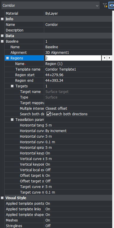
If you have many templates you wish to use, it could be faster to split the corridor (CORRIDOREDIT → Split Region) at correct locations and then set the templates through the properties panel. You can set the start/end stations, template and some other things by selecting the corridor and then clicking on the 'Regions' and selecting the correct region. Then you can click on the 'Template name' and the '…' button to select a different template (or if you know it's name you can type it directly).
Similar to how you can have multiple regions for each corridor, you can also have multiple 'baselines', that can be useful if you're trying model/visualise some more complex cases (like intersections).
Since in the initial post you have an image of superelevations, this is unfortunately not supported. I guess the easiest way to have some control over this is to use 'string lines' as vertical targets for some of the corridor template element points. Maybe this link will give you an idea on how to use the targets.
0 -
Yes when using Civil Site Design it uses "string lines" so you can simply apply say superelevation to strings, A simple road would be 3 strings Left, Centre, Right, you actually give them names so a rural road would have LSH, LEB, CL, REB, RSH. The super table allows you to use those string names, On top of all that the strings can be independent horizontally as well. This type of designing has been in CIVIL software since about 1980. I know because I was a state rep for one brand. Bricscad has a bit of catching up.
0

