Anyone with experience in 3D scanning?

We're just a small firm, and don't even have a CMM. I had to make at least 100 measurements of the chassis with calipers, mikes, gauge pins, etc., before I could create the drawing. We have no other mechanical designers here to check my work. You can imagine the concern I had about measurement error. And it also occurred to me that the one piece I had access to, might not have been nominal. Would the part I designed mate correctly with the other half of the chassis on a consistent basis?
Now they are telling me I will likely have to reverse engineer a much bigger, much more complex chassis. So I am looking for a way out of this mess. Some metrology companies are offering 3D scanning for a fairly hefty fee. Has anyone here had a chassis like this 3D scanned? I'm particularly concerned about flexing and warpage in the chassis. Would that cause the CAD drawing to become an unusable mess of arcs rather than straight lines?
I am considering also whether I could flatten a chassis and measure that instead. I don't know if I could completely remove all the creases at the bends, detents, stiffining bumps. Has anyone done anything like that?
I know the best thing would be to negotiate an agreement with the OEM for the original drawings. But I don't think our management is going to go for that.
Comments
-
do you know a surveyor with a scanner?Or ask an instrument seller to demonstrate.Topcon, Leica.It's an interesting subject. I've read about teeth being scanned in dental work.It's one of our modern innovations that has many applications.0
-
0
-
3D scanning, despite all its future promise, is still difficult to use for reverse engineering. It is one thing, if you want to scan a person's head to make a 3D printed model, but if you want to scan a sheet metal part and then expect to use the results for making another sheet-metal part, I doubt you will save much time and effort over your existing approach.Here are some of the issues;A circle is not a circle in a scan. Rather, it is a series of flat faces.A large flat surface, is not a flat surface. Rather, it is a collection of faces that almost lay in a plane, but not quite.Something may be drawn as a 1/2 radius, but may actually be .49" on the manufactured part, and then on the 3D scan, it comes out to .48".Most canning systems cannot generate a model of the entire system at once, because some parts will be hidden from the scanner's view. Stitching software is not as common in low-cost systems.Of course, there are ways to work with the above issues, but the question is if all that work is really less time consuming than just getting out the calipers and doing everything manually.The good news is that scanners are now cheap enough, that it may be worth playing with one, just to see if you can figure out a good, efficient, work flow. It may be that you can use the scan as a basis for tracing or measuring the item in BricsCAD.Here is a link to one system, the David Scanner, which does have a free version It was one of the first low-cost system out a few years ago. It uses a hand-held laser and a standard web cam. But, in this system, you need a printed background, because it provides the calibration targets. If you go to the download area, you can get the free version. The free versions main limitation, is that once the trial period is over, it will not be able to stitch multiple scans.www.david-3d.comI am sure there are a zillion other low-cost or free scanners out there now.0
-
Hello Jim,
I think Joe is right - scanning produces point clouds, which can without much fuss be turned into meshes, but hardly into analytical geometry... for reverse engineering, I think the professional way to go is digitizing (Faro, Microscribe...), since it allows you to sample only relevant points and then model 'from scratch'. But these devices are costly, and I don't think there are interfaces to BricsCAD (more a domain of rhino).
So, if I had to do such things (and I'm glad I don't), I would rather use a caliper to get overall dimensions right, and then model on top of reference photographs, taken with minimum perspective distortion possible, and perhaps additionally corrected in an image editor.0 -
I have no idea of the size of the object, but back to a surveyors input.I've surveyed a lot of structures for design purposes including an odd shaped truck tray and underside of bridges to build prefabricated walkways and milk vat to determine distortion during emptying/filling.If it's of a scale that makes it worthwhile, then engaging an understanding surveyor with your own input could be very beneficial.I imagine there would be critical areas where tolerance is non-existent so ensue measurements are taken along with sufficient others to check for bulges, misalignments etc.Done accurately and with due care and checks with a tape measure you should nearly be able to "create a plaster cast" as we often call such a level of detail.If you have 'flat' surfaces they could easily be checked for twist or evenness, alignment etc.Once data is collected it's a piece of cake to deduce all manner of measurements. That is where check measurements can verify the accuracies.But this does depend on scale.I'm imagining something several meters long, possibly similar wide. As said, I'm guessing on that.0
-
I have moved a branch on the thread the thread titled, "Importing a STL file"https://forum.bricsys.com/discussion/23543In Blender, polygon count reduction is done via a modifier called 'Decimate'.
...
The 'Decimate'-modifier offers three different algorithms (Collapse|Un-Subdivide|Planar), but all of them work better on dinosaurs than on mechanical parts..Ideally, software for processing scanned images should have a certain level of intelligence to it, to recognize corners, holes, flat surfaces. About 12 years ago, I investigated the possibility of doing a 3D scan of a very large theater, for the purpose of creating an accurate as-built 3D cad model. Some expensive scanning software promised the ability to do things like recognize pipe, I-beams, C-channel, etc. But, when I spoke to a company that specialized in doing scans of buildings, they said the never use those features, because they don't really work. Rather, they use the scan results to draft a 2D view, or to make measurements they use to create a 3D model manually. In the end, we just hired a surveyor to survey a number of points in the theater, and I used that to manually create a 3D model based on the 2D CAD files we already had.Hopefully the software has gotten better at automatically processing things, and perhaps there is software that can recognize a relatively flat surface and then model it as a flat surface. It is probably especially challenging for the software to recognize a round hole, and then to model it as such, when it only sees a little of the inside surface.Rethinking my original reply;Mr. Canale, as I think more about the original post, and my reply, I think I may have been overly negative about the benefits of scanning. Upon rethinking my position, I suspect yo9u will benefit from using a cheap scanner. But, it would be only as part of the tool set. Here is how I would proceed.Perhaps you take a 3D scan of one side at a time, and then puts the resulting mesh into model space, and trace over it in paper space. If you are tracing over ventilation holes, then you know you don't need precision. But, if it is an important mounting hole, then measure it with the caliper.The final step would be measuring overall width, and other things that might be a challenge for the scanner or require a lot of post-processing. Then, use the earlier tracings and put the whole unit together. You can also edit the mesh to cut away some portions, and then you can see and trace over a more complex bend.2D Scans;I will mention some other related methods I have used. The easiest (if you have a large enough flat 2-d scanner) is to simply scan a side. You might do it a portion of the side, and then stitch the results. With todays high mega-pixel cameras, it is viable to just take a picture. But, you really need to use a long telephoto lense, and take the picture square-on from a distance. That is, unless you have some sort of software to adjust for the fish-eye effect.With a 2D scan, you could either paste the image into the cad drawing as the basis for tracing, or you can use some vector tracing software available in many programs. But, that will still require a lot of re-work because the software is likely to draw a round circle as a polygon. But, it is dirt cheap to do, it would be easier than manually measuring all those holes.Photogrammetry;There is a final method I will mention for digitizing 3D objects. That is to use photogrammetry . This where you take multiple photos, and use specialized software to digitize the object in 3D. I have not done anything in that field, since I worked at an accident reconstuction consulatant, some 15 years ago. The software I used as PhotoModeler by Eos Systems. At the time, you essentially had tools to trace over object by clicking on common points in multiple view. It had software to calibrate for any camera. There were special tools for drawing circles. I know there has been significant advances in this field since then, especially with automatic processing of scene. But, its real field of usage is more in the organic world, rather than mechanical engineering.Here is a quick link to an article on some free software for this. Note that your object needs some good targets. A smooth surface is generally not a good one. Your software needs to be able to see and identify unique points. But, that is readily handled by making marks on the object with stickers or a marker.Here is an article listing a lot of photogrammetry programs and providing a rudimentary comparison.-Joe0 -
Me too, I have been rethinking my cited statement (decimating dinosaurs):
reconstructing 'solid' geometry may to some extend be feasible, see attached small experiment in blender, if you like (sorry for the nearly 5MB file).
I do not have access to scanner data, so I took a 10x10 unit plane, subdivided it and added some noise. Then I applied the three built-in algorithms that blender offered: first 'Collapse', then 'Un-Subdivide' and finally 'Planar'. The first two do their job nearly in real time, and give probably neat results when applied to dinosaurs. The last one is much slower, but with a tolerance value of 45 degrees, it reconstructs the original plane perfectly - with an accuracy of 1/10000 unit, which I found quite surprising...0 -
Me too, I have been rethinking my cited statement (decimating dinosaurs):
reconstructing 'solid' geometry may to some extend be feasible, see attached small experiment in blender, if you like (sorry for the nearly 5MB file).I could not open the decimate.ogv file in Blender. Is ogv the correct file extension?Also, when I looked at the options for simplifying a mesh in Blender, I found this in the manual, comparing Decimator with Poly Reducer. Though, I can't seem to find either feature in Blender 2.7.Poly reducer has some advantages and disadvantages compared to Blenders decimator modifier, here are some pros and cons.
Pros
- Higher quality resulting mesh.
- Can operate on any mesh, will not throw errors if the mesh has odd face/edge/vert topology.
- Options to control where polygons are removed.
- Keeps materials assigned to faces.
- Maintains UV Texture coordinates, Vertex colors, and Vertex Group Weights (used for bone weight painting) - This makes it very useful for game/realtime models.
Cons
- Fairly Slow
- Uses a lot of memory
-Joe0 -
Hello Joe,
ogv (also called ogg) is a patent-free video format, that nearly made it into the HTML5 standard (was dropped due to resistance of some big players).
I did not realise that it is not automatically recognized on windows - I guess the windows media player will not have the necessary codec then.
The file contains a screen capture of the decimate modifier in action, it would probably also answer your question where to find it.
The poly reducer script was to my knowledge only available up to blender 2.49, and has probably meanwhile been superseded by the decimate modifier.0 -
Here I am apologizing again, for asking for your input and then leaving the thread unattended several days. (I was out sick.) Sorry.
Thank you all, for your comments and suggestions. I have much to mull over. I didn't expect so many suggestions for scanning... I had already located an outfit doing white light, high resolution scanning, that is supposedly more accurate than laser. Exact Metrology. They claim their software will take some warp and twist out of the sheet metal chassis. But it is a fairly expensive process. And I had my doubts whether it would deliver a usable 3D object BricsCAD could edit. I'm concerned, as Joe mentioned, that I would wind up with an enormous "cloud of points". I've already learned that BricsCAD does not handle high complexity meshes well. Conversions from STL, STEP, IGES are problematic too. I have some experience with Automesher and Communicator.
Richard, I didn't know surveyors used scanners these days. I was a surveyor in the early 70's. We were still using transits and taping distances then! Not sure a scanner used to map out large distances would offer enough resolution for a small chassis. But I will see what the industry offers.
Dennis, I will have to look further into the Cubify hand held scanner. This might be the ideal device to scan one side at a time, if it offers good enough resolution. Another concern is specular reflections from the metal. But I think I could paint the thing with a dull, non-reflective paint.
Joe, I will look also into the David Scanner. You and Knut have some good ideas on converting the files........
I still wonder if my other approach (physically flattening the chassis, and scanning it on a 2D scanner would offer the best results. That process would give me a "developed blank" The material is soft, thin aluminum. But I am not sure I could do this without stretching the material. I also don't know what kind of accuracy I could get from a 2D scanner, and whether I could accurately stitch scans together. The part will be too big for an 8 1/2" x 11" scanner.0 -
Here I am apologizing again, for asking for your input and then leaving the thread unattended several days. (I was out sick.)No need to apologize. The party obviously continued without you.You started a topic many of us share an interest. We all would love an affordable magic box that we activate, and it generates a perfect CAD file for us. Most of the stuff at Exact Metrology does not have a price listed. This implies that, "if you have to ask the price, you can't afford it". Sometimes the higher cost item is actually less expensive that going cheap, because of the labor or hassle involved with a cheaper option. And sometimes, the expensive option becomes even more expensive if it also involves a lot of labor and hassle.So, be sure to test the full process from start to finish, with parts of your object, before you invest much money.Please give us a report back, letting us know how you decide to proceed, and how it turns out.-Joe0
-
Thanks Joe. Right now it is in the hands of management. When I have something, I will let everyone know.0
-
I use Artec spider for quality control of aircrafts, and developing individual repair parts for them. You know real aircrafts we have are different from each other so no existing CAD models are suitable for them. So I'm that guy who scan the current part of a jet and provide data for engineers to work with. If talking about scanner and scanning process, it's kinda complicated to perform a proper scanning, I had to train a lot.
0 -
Joe,
Everything you said is true. We were also told that certain parts, like shiny sheet metal or clear plastic, are very difficult to scan accurately. Reflections, etc. For that reason we continue to manually measure housings that we want to reverse engineer. It is a very tedious process, and we never know if the part we are measuring represents the "nominal", or an extreme limit of the tolerance on the part.0 -
BubbleB,
The Artec is too pricey for my employer. We are just a small family owned business, and sales have been very slow since the economic downturn. I'm sure there is a great deal of training associated with getting a good scan. Maybe the guy who replaces me will be able to bring the company into the future.0 -
Joe, for photogrammetry, https://www.capturingreality.com is the new kid on the block - a heavyweight thing with algorithms that are 10x faster than other leaders (tho they will surely catch up) thus requiring a much more modest computer. Full-license price is as stonkin as the others, but for the time being, as well as feature-limited free Trial, there's full-featured version @ E99 per 3month.
Skill of course has to be acquired - but the online public forum is as good, fast-response and understandable as any, as is the co's Support response - which is a lot more than can be said for e.g. Adesk and Bentley's equivalents.
People have made fractional-milimetre models of the tiniest of complex objects - extreme accuracy depends only on resolution, sharpness, lack of 'noise' etc of the photos, and the routine for getting the right photos.
Output can be point cloud, mesh or fully photorealistic. I haven't yet ascertained how to bring a model into Brics - or indeed if possible until Brics delivers (promised) point-cloud enablement - but perhaps mesh may be possible already (and snappable).
0 -
An option we are using to do highly accurate scanning is Creaform's products. We started with a revscan, and have since moved to the new Handyscan 700. You could find used revscan, or handyscan models on ebay with software for as little as $6000,00. I am not sure the size of the products you are scanning, but these scanners are accurate to .01mm within the envelope of a cubic meter. They are capable of scanning very large objects easily. They offer support packages for any scanner they have ever sold, so you could buy a used one, and pay for full support as if you bought one new. To overcome the issue of shiny, and smooth object scanning, you simply need to spray them with a developer powder. It is thousandths of an inch thick when applied, and provides an ideal finish to scan. it can be washed off easily. The software that comes with the scanner can output a mesh that can easily be imported into bricscad if you have communicator.
0 -
@motoman666 said:
An option we are using to do highly accurate scanning is Creaform's products. We started with a revscan, and have since moved to the new Handyscan 700. You could find used revscan, or handyscan models on ebay with software for as little as $6000,00. I am not sure the size of the products you are scanning, but these scanners are accurate to .01mm within the envelope of a cubic meter. They are capable of scanning very large objects easily. They offer support packages for any scanner they have ever sold, so you could buy a used one, and pay for full support as if you bought one new. To overcome the issue of shiny, and smooth object scanning, you simply need to spray them with a developer powder. It is thousandths of an inch thick when applied, and provides an ideal finish to scan. it can be washed off easily. The software that comes with the scanner can output a mesh that can easily be imported into bricscad if you have communicator.motoman
That sounds really intriguing. Although I don't know how to turn a mesh into an editable solid object with BricsCAD. I'm curious how big the files might be to scan one of our thin housings, which may be up to 19 x 12 x.5. We need accuracy to .002".0 -
Have you tried sketching from an image.
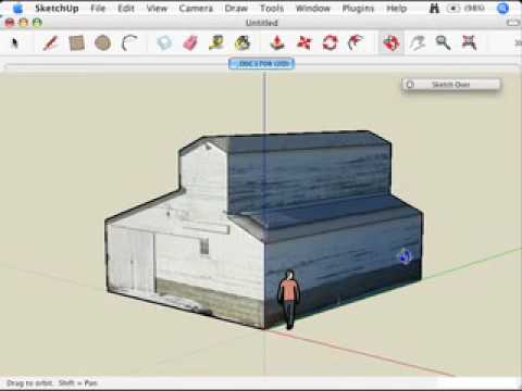 https://www.youtube.com/watch?v=fSuDoX8SPtU0
 -
This is now a somewhat stale thread, but I saw this in my "Drafts" folder, and see that I never actually posted it. I was probably having internet issues, or the BricsCAD forum was down by the time I originally was ready to post. Anyway, in case it still has any useful info, here you go....
@Jim Canale said:
I still wonder if my other approach (physically flattening the chassis, and scanning it on a 2D scanner would offer the best results. That process would give me a "developed blank" The material is soft, thin aluminum. But I am not sure I could do this without stretching the material. I also don't know what kind of accuracy I could get from a 2D scanner, and whether I could accurately stitch scans together. The part will be too big for an 8 1/2" x 11" scanner.Upon re-reading the thread, I agree that this may be the best option. Sheet metal work is not a process that is considered highly accurate. Yes, there may be some distortion, but you will probably need to do some test parts and then adjust dimensions if necessary.
For a time I was creating 3D CAD models for a theater. I would start by measuring a small model of a theatrical set piece. I briefly considered a 3D laser scanner, But, I immediately realized that I wanted to model to have walls that were perfectly flat, and perpendicular to the floor. And if something were 6.1 " from an edge, I was strongly motivated to change that to be 6" exactly. .... well unless that 0.1" of space was for clearance to another part that had to go there at a later time. No machine is capable of making those kinds of decisions.
In other words, I really did not want to accurately re-create the object. I just wanted the tools to make it faster for me to re-interpret the object, and make it easy to interrupt the process to insert my own design skills. There were some parts of the object that didn't need to be very accurately reproduced. These were areas like the part of the set that depicted the perimeter of the ground around a rolling set.
For your work, you have a part that is known to work well. Ideally, you would exactly reproduce it. But, keep in mind that even if the part works, it is not really produced as it was drawn. There are always manufacturing variations. Ideally, you would want to model the original design intent. But, sometimes that is not possible to really recreate, nor necessary.
For my CAD modeling of the theater's physical models , I ended up buying a small, used, MicroScribe digitizing arm for $600. I also had a small end-tip created to attach to the MicroScribe, to make it easier to point to a corner of two walls and get the theoretical corner.
Before obtaining the MicroScribe, one method I used to measure a set piece with an irregular base, was to simply place the base of the object on a 2D scanner, and then I imported the image into my CAD system. After scaling it properly, I just traced.
As for the scanning of a 2D part, tabloid sized scanners are not uncommon. This makes it easier to do larger sizes. Just look for a Tabloid sized multi-function office machine. The scanner part is probably 11"x17". But, stitching works well also. Just add some marks that will show up on the overlap areas if the area doesn't have any detail.
I have also used digital cameras for "scanning" a large object. But, they introduce some distortion, so it is advisable to use a telephoto lens and get as far away as you can from the object. This can greatly reduce the distortion. There are ways to adjust for distortions in image editing software, and you might draw straight lines across your part to help facilitate this process.
With the 2D scan, don't expect a push-button solution. Rather, use the image as a guide that you trace over, and then edit the dimensions to have them make more sense. E.g. a 0.501" diameter hole is probably better modeled as 1/2".
Your own work flow and tools will, of course, need to be chosen to work well for your own situation. But, this can take a long time to really refine, and will probably take a more time than you expect.
-joe
0 -
@Joe Dunfee said:
This is now a somewhat stale thread, but I saw this in my "Drafts" folder, and see that I never actually posted it. I was probably having internet issues, or the BricsCAD forum was down by the time I originally was ready to post. Anyway, in case it still has any useful info, here you go.............................................
Joe,
I never got back here. So belated thanks for your post. I will have to look into the Microscribe. I have used a 2D table top scanner with mixed results. I have also imported pictures from a digital camera and used them as a reference for my 2D drawings. Of course you have to scale the picture properly after you bring it in. The way I figure out the scaling factor is to measure one linear dimension on the object accurately with a ruler, caliper, etc. and use that measurement to scale the whole picture. I've been bitten by barrel distortion, perspective distortion, etc. So your suggestion to use a telephoto lens is a good one.
0 -
One thing I recall about the Microscribe. You only have a point to digitize a point. But, I often wanted to digitize the corner of an object, or the center of a hole.
So, I asked our machine shop to make a special tip for me. The one for the corner was shaped like a 90Deg V.
The one for centers of holes would simply be a cone. Though, I ended up not actually having it made, because we would have needed it so infrequently. You would have to ignore the Z-value. This "ignoring" is made possible because I used the Text Interface version of my Microscribe. This means it would simply type the coordinates of a point into whatever program I was using. I recall that it was possible to configure how it would type them, so I had to configure it how AutoCAD wanted to see it. It was possible to have it omit the Z-value.
-Joe
0 -
Thanks Joe. I checked Microscribe's website, and the cheapest machine that is currently in stock is $12K. They apparently had a lower accuracy model for less, but that has been discontinued. Knowing my employer, I doubt they would pony up more than 2G's for a unit. So I will have to look on the used market.
0 -
The one I had was used as well. It is a precision, well built, machine, that people tend to take care of. So, I would not be afraid to buy used.
It was perhaps purchased in 2003, and was around $700. Note that it had a serial interface, not USB. A USB-to-Serial converter solved that. However, I don't know if the software interface for the old machines would work on a current Windows system. So, I would do some checking into that.
-Joe
0 -
Thanks. I will shop around. Right now however, I am trying to make the case for a faster PC. So this will go on the back burner.
0 -
For high scanning offerings I recognise a Scanning surveyor who provide scanning in wide fields llike document management Scanning.
0 -
I think Joe is right - scanning produces point clouds, which can without much fuss be turned into meshes, but hardly into analytical geometry... for reverse engineering...
Right now I use Geomagic Design X as it helps a lot to turn point clouds to parametric solid models.
It's still not "one button click action" but it makes the process much easier.0 -
My employer never bought a machine. I put the part on the surface table, and measure with height gauges, micrometers, calipers. If you know the original measurement system (inch or metric) it's a matter of saying, "Was the intent of the designer to space the mounting holes at 100 mm, or 100.05 mm?" Of course this only works on very simple objects.. I'd hate to do a lofted surface without a CMM.
0 -
I imagine a program like Geomatic Design X is very helpful. Much of the design for an object does not need to be very precise, and has fairly large leeway. And any sort of automation helps the process.
But, certain items, such as the mounting holes for a motor, need to be more precise. But, even that precision is not intended to be a precise measurement of all the holes to one edge of the mounting plate. Often it is only important that the mounting holes be accurately placed. in relation to each other. In other words, the design intent is something that only a designer can decide.
-Joe
0 -
I am sorry I'm writing in an old thread, but as there are probably some people who are choosing a 3d scanner, I'd like to share two portals with reviews, and good reviews of 3d scanners. This guy who seems like he get scanners for a review, so he shows what he get from this equipment. Probably one of the most helpful reviews.
And this who is more about technical data, but good structured, so if you are looking for exact info it's also a choice.0

