Slice / Subtract Sheet-metal part

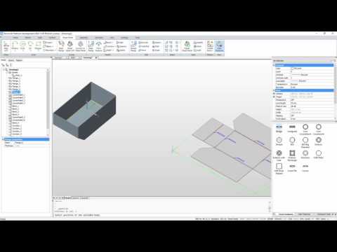
attached you'll find a picture.
How can I subtract the lighter grey part from the darker part with the bend ?
Thanks
Steffen
Comments
-
The obvious answer: use the _Subtract command.0
-
Thats what I tried. Unfortunately it isn't working. Errors shown in the attached image.
This happens after selecting the bended parts to subtract from and selecting the lighter grey part to subtract.
Any ideas ?
Thanks test.JPG0
 -
Perhaps the light grey element is not a 3D solid but a 2D solid with a thickness.
If that is not the case then you should post a dwg.0 -
Thank you for your support Roy. I'm a newbie in 3D modeling. Attached you'll find the dwg file.
Best
Steffen0 -
There is only a single 3D solid in the dwg. The _Subtract command requires at least two separate 3D solids.
I do not have experience with BC Sheet Metal, but here are two approaches that can work:
1.
Use _DmPushPull. You can push a 3D face so that a 3D solid becomes smaller. With this method you can completely remove the light grey 'flange'. The bend can next be removed in the same manner. Finally you will need to remove the bend relief. Again _DmPushPull can be used.
2.
Create a temporary _Box and use _Subtract. With this method you can remove the flange, the bend and the relief in one go. You can then use DmPushPull to adjust the width of the remaining 3D solid.0 -
Sorry don't get that.
Isn't there any possibility to slice / cut the light grey part away ? It should just align to the bends / flanges.0 -
Is this what you want? Just did a push/pull on the side.0
-
Hi Patrik,
no - thats how it was before I extruded the side to the flanges.
I just want to get rid of the light grey triangle.
Thanks.0 -
At the end - it should look like in this picture
 test2.JPG0
 -
What about this?0
-
Great - thats what I'm looking for.
How is it done Patrik ? Need to do it on all for sides and don't want to die dumb") 0
0 -
Perhaps:
1.
Using: _SolidEdit > _Edge > _Copy
Copy the 3 edges (2 straight and 1 curved) that make up the inner seam to the outside of the flange.
2.
Make sure that boundary detection is enabled (SELECTIONMODES).
3.
Hover over the outside triangular area that is now enclosed.
4.
Use _DmPushPull to remove that part of the 3D solid.
5.
Erase the 2D elements created in step #1.0 -
Actually there is a small inaccuracy in the model: there is a 0.00106 gap between the front flange and the flange on the right. If you correct this error with _DmPushPull this is also possible:
1.
Make sure that boundary detection is enabled (SELECTIONMODES).
2.
Hover over the inside triangular area.
3.
Use _DmPushPull to remove that part of the 3D solid.
4.
Use _DmPushPull again correct the position of the 3 new faces.0 -
Retesting my solutions I realise that I have sometimes actually used DmExtrude instead of DmPushPull.0
-
Wow - thank you so much for your help Patrik, really appreciate it.I need the sides to be aligned to the outer edge of the flange though. I will try your ideas tomorrow.Thank you again Patrik - you're awesome.CheersSteffen0
-
This is what Roy is talking about. If you just extrude the side to far the other flange does not match up so you can not take away the excess. I shot it back 20mm to be able to grab it later then pulled the side to far, finally pulled the first side up to the flange. Now I can push away the excess. But also notice that the solid melts together in the corner. Maybe lofting can take care of this.
https://drive.google.com/file/d/0B5ou0c4CSi7yLUdnTHE2UUppYnc/view?usp=sharing
0 -
This 'melting together' seems to be a side-effect of _DmPushPull. To avoid this you can use _DmExtrude instead.0
-
Learning so much - thank you guys.
So far - I'm very close to what I need. The sides need to be aligned on top of the flanges so that the edgeof the side stays visible.
Using your method basically cuts away 1.5mm too much from the sides. They need to overlap the flanges.
I hope you understand
Cheers
Steffen0 -
Post #15 (skip step #4). But, as mentioned, in some steps use _DmExtrude instead of _DmPushPull.0
-
To fix the corners check this video0
-
Hi Patrik, Hi Roy,
tried the latest ideas now but as you said - the 3d solid melts together on the edge.
I've tried both commands dmExtrude and P&P. Both seem to have trhe same effect.
This way I can't add another flange like on this picture...
More idea welcome")
 test3.JPG0
 -
Actually this annoyed me, tried to solve it yesterday , no good but woke up having solved it. Had to make an offset 1mm as it would not use 0. Also push/pulled fixed repeatable distances, finally retracted 19.9 instead of 20 to keep a 0.1 gap . Im working on a cabinet so it was useful for me as well.
https://drive.google.com/file/d/0B5ou0c4CSi7yaW5HejJxdXpOOVE/view?usp=sharing
0 -
From my point of view the best way to model this - is to shell a solid body and then convert it to sheet metal0
-
So many ideas - thank you all.
Tried your idea Patrik, worked perfectly - many thanks for helping me out on this.
Will now try Ilya's idea as well.
Great to see so many helpful people in this forum.
Cheers
Steffen0 -
From my point of view the best way to model this - is to shell a solid body and then convert it to sheet metal
Looks like dmchamfer only does 45°.
Using custom angled chamfer on solids seems to be another lesson...0 -
Looks like dmchamfer only does 45°.
Using custom angled chamfer on solids seems to be another lesson...Yes, it is does only 45°, but you can easily dmRotate this face...0 -
Video (animated gif) of the solution proposed in post #21.
 Test.gif0
 -
Hi Roy,
your approach isn't working for me.
Can't find a gap on mine and I can see the selected boundary.
When I push&pull the triangular part away my solid melts in that part.
Something wrong here I think.0 -
There definitely is a gap between the two flanges (dwg from post#5). You may have to change your LUPREC setting to be able to measure it. It is small but large enough to prevent the detection of the triangular boundary. The 'melting together' does not occur in V17 if you use _DmExtrude. So I think you must be using V15 or V16 where this indeed happens.0

 https://youtu.be/qSNmJnVo0zI