Dynamic Block

Hello,
I know BC doesn't allow editing dynamic blocks. I have searched the web trying to find an add-on or something (can be payable) and failed.
Has anybody bumped in a such piece of soft for BC?
Cheers,
Jan
Comments
-
Autodesk has apparently been able to patent their creation and editing of dynamic blocks so to prevent others from creating something that works to create dynamic blocks.
While GStar CAD, in China can create and edit dynamic blocks, it can legally only do so where the patent law permit it. In China patents last 5 years. They should not be permitted to include that feature for any licenses sold in the U.S., where patents last much longer. Though, China is not a country known for respecting patent or copyright law. Though, in recent years, they have been doing more to comply with international law. But, certainly don't expect them to respect your own drawing property, if you buy their software for use a country that has a longer patent duration. Even if is legal in your country to buy, China 's government is know to sponsor corporate spying to boost their own businesses. So, you may well be giving your work to the Chinese government.
Another approach is to just subscribe to AutoCAD for a month, and create and edit any blocks you need to. Though, of course your need to do so is probably sporadic. Or a related approach might be to utilize a drafting service that has AutoCAD to do any of these changes.
I ended up approaching my need for something like a dynamic block by creating a spreadsheet with a VBA routine that would use the data in the spread sheet. It is posted on the following thread.
https://forum.bricsys.com/discussion/32858/a-working-excel-spreadsheet-with-vba-to-draw-objects-in-bricscad#latestAlso, note that support for using existing dynamic blocks inside of BricsCAD has improved over the years. My v14 does not support tables, but the most recent version of BricsCAD does.
-Joe
0 -
Don't use em myself, but I thought there's been much coverage lately of how Brics has at last cracked it, either already in v18 or imminent?
0 -
Joe, many thanks for the explanation.
I am on v18, dynamics blocks work flawlessly but lack of editing mode doesn't help.0 -
@Tom Foster said:
Don't use em myself, but I thought there's been much coverage lately of how Brics has at last cracked it, either already in v18 or imminent?Do you have a source for this coverage
-Joe
0 -
At recent Brics conference I think - anyone?
0 -
I was at the Bricsys Conf in Oct 2017 and I don't recall any news like this.
Dyn Block creation is not in v18 and AFAIK, not imminent.0 -
Can Bricscad explode dynamic blocks?
0 -
Hi,
Not necessarily .
If there are constraints used, BC won't explode, otherwise yes.
I'm having a lot of issues with dynamic blocks currently.
Our Structural Engineers uses them a lot.
I have a bunch of good ones for architecture, so it is a pity BC will never have editing ability.0 -
Never say "Never"
") 0
0 -
@Tom Foster said:
At recent Brics conference I think - anyone?I think (and hope) there is much more potential in pursuing the capabilities in BricsCAD Platinum. I think this is what they may have alluded to at the conference. Platinum already has the capability of creating different types of 3D & 2D dynamic blocks. What is missing is the interface to make it more accessible to the user.
Regards,
Jason Bourhill
CAD Concepts0 -
@Jason Bourhill:
Is that a dynamic block created in BricsCAD? And if so: how does that work?0 -
Wasn't it an alternative approach, similar result - using parametrics?
0 -
@Roy Klein Gebbinck said:
@Jason Bourhill:
Is that a dynamic block created in BricsCAD? And if so: how does that work?Tom is right. I essentially created an assembly of the sub elements of the North arrow, applied suitable constraints and paramters. I actually find this easier to do than defining a dynamic block in AutoCAD.
I think a lot of the underlying functionality is now there in BricsCAD Platinum, V18 has arrays & lookup tables. And as you pointed out previously there are more functions available when working with constraints & parameters. What is missing is exposing this functionality through the interface to make it more readily available. Currently you have to move from the drawing area to the Mechanical Browser or Property Bar to make changes. I used a rough bit of LISP to work directly with the visibility of the object.
If you are playing with the attached files, Then you need:
- BricsCAD Platinum for full access.
- BricsCAD Professional will allow you to modify the arrow directions, but not the visibility.
- BricsCAD Classic doesn't provide any access.
Regards,
Jason Bourhill
CAD Concepts0 -
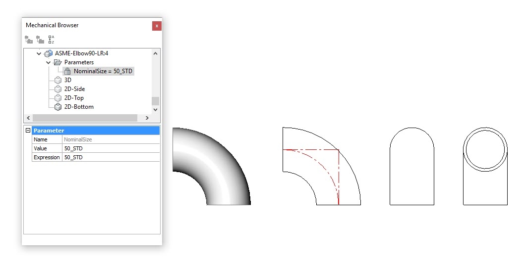
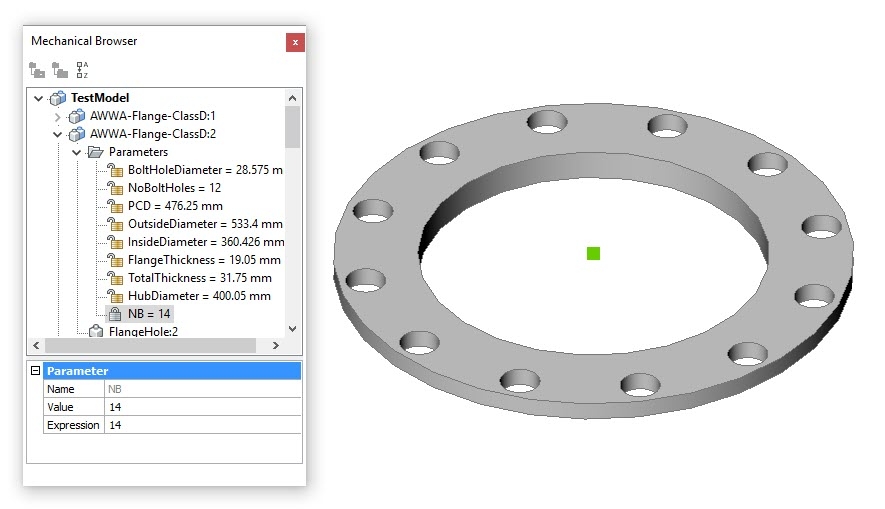
Here is another example using a pipe elbow & flange. The elbow is to demonstrate that in BricsCAD the dynamic blocks can be 2D or 3D. Flange uses an array to cut the bolt holes. Both are linked to a lookup table for selection of different sizes.I think I made a mistake with the flange, at smaller sizes the holes go outside the flange OD. I haven't gone back to check, but I think I may have made a mistake when entering the data for the lookup table.
Regards,
Jason Bourhill
CAD Concepts0 -
This is example of a parametric bar stool is a little of topic, but has some other aspects that I've played with. It uses constrained 2d lines as guides for the pipe pieces. This highlights that you can apply 3D constraints to 2D objects, and that in some cases it is easy to create a dummy object to assist in getting the model to move the way you want. The attached LISP allows you to turn these hidden objects on/off.
Because of the design, there are limits to how low the stool can be for different pipe sizes, pipe radii, and stool depth. Here I use functions to limit the movement to what is possible.
Finally, it has a lookup table for different stool options.
Regards,
Jason Bourhill
CAD Concepts0 -
@Jason Bourhill:
Thanks for sharing. Your contributions truly showcase what is currently possible. And using _BmShow to emulate visibility states is a clever idea.I have yet to study the material in more detail, but already have two questions:
The barstool model is somewhat complex with ca. 100 constraints. Constructing the symmetrical frame from 2 or 4 sub-components seems possible and would reduce the complexity of the final model I think. Have you considered this?
And why have you used surfaces parallel to the main planes of the WCS? As you know you can directly use subentities of the WCS.0 -
@Roy Klein Gebbinck said:
Using _BmShow to emulate visibility states is a clever idea.Thanks, it's a pity that this particular functionality only works in Platinum. If it was made available it would give a more consistent experience to those running at lower levels.
The barstool model is somewhat complex with ca. 100 constraints. Constructing the symmetrical frame from 2 or 4 sub-components seems possible and would reduce the complexity of the final model I think. Have you considered this?
And why have you used surfaces parallel to the main planes of the WCS? As you know you can directly use subentities of the WCS.The reason is that I started this model back with V16 when some of the features you mention weren't available. It is a bit of a frankenstein model, the result of trying out ideas over a period of time. The model actually started life as a simple hairpin! I would certainly create it differently if I was starting again in V18.
Mainly I posted it to show that you can have lots of parameters with functions + design tables and it will work. It shows how far things have come in a few versions. Yes, it is unnecessary complex, but V18 will happily deal with it.
You'll notice looking at the limiting functions that they aren't static limits, but are dynamic. The limits adjust depending on the input parameters.
Regards,
Jason Bourhill
CAD Concepts0 -
Hello
I'm french so sorry for my english!
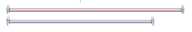
I'd like to create a dynamic block with this file.
The idea is to be able to change the component to an another one.
Is that possible on Bricscad V18?0 -
@Mrick44:
To avoid confusion we should not use the terms 'dynamic blocks' and 'parametric components' interchangeably.Your image seems to depict a scaffolding element. You can definitely create a parametric component for such an element (see the attached file).
But scaffolding elements are usually standardized so parametrization may not be the right approach.0 -
Actually, the upcoming version of ZWCAD 2019 will allow You to create and edit dynamic blocks!
0 -
Since patents in China are shorter-lived, they may be able to work around some of the Dynamic Block issues. But, I don't know if they can legally sell that technology back to countries. where a patent may still be active... not that China has any concern about honoring patents in other countries.
-Joe
0 -
It may not be the solution I am looking for.
Especially that ZWCAD, GesterCAD etc. are less reliable than BricsCAD.
Not the best forum for such suggestions though.
J.0 -
@Roy Klein Gebbinck said:
@Mrick44:
To avoid confusion we should not use the terms 'dynamic blocks' and 'parametric components' interchangeably.Your image seems to depict a scaffolding element. You can definitely create a parametric component for such an element (see the attached file).
But scaffolding elements are usually standardized so parametrization may not be the right approach.Thank you, but I use blocks to realize my plans. At the end of my work I use the data extraction function for Bricscad to pull out a list of drawn elements. I do not think that with the solution that you propose to me I can give a name to the elements of different lengths?
Thank you0 -
@Mrick44:
First of all let's keep things straight: In my previous message I was commenting on your suggestion and already expressing doubts. So the idea of using parametric components is not my proposal.To clarify my doubts:
If you are working with a set of standardized components, and you do not want to use 3D constraints to position components, or have any use for the features of the _BmBom command (volume, weight), then using the BricsCAD component mechanism does not make sense.
It is much easier to create a variant of a component with the direct modeling tools than to do so with parametric constraints. And instead of using _BmInsert you can just keep using the 'normal' _Insert or _Xref commands.The _DataExtraction command can also be used for parametric component though. And you can in fact give a unique name to an instance of a component and extract that name.
Your initial question perhaps stems from a lack of experience with the direct modeling toolset. To stretch a 3D solid you do not have rely on 3D constraints. If you _DmMove a selection of faces, connecting faces will be stretched to accommodate their new position.
0


