Modeling Sloped Slabs

Trying to figure out what’s the best way to model sloped slabs.
Ideally, our workflow would be to form our entire flat slab, add or remove vertex points to the top/bottom faces, drag those vertices in the z-axis or laterally as needed.
The closest way I’ve found is using a mesh for the slab object, but then in BricsCAD BIM, sections cut through the slab won’t show material fill since it’s not a solid (I’m aware that converting to solid is possible, but then vertices are no longer easy to manipulate)
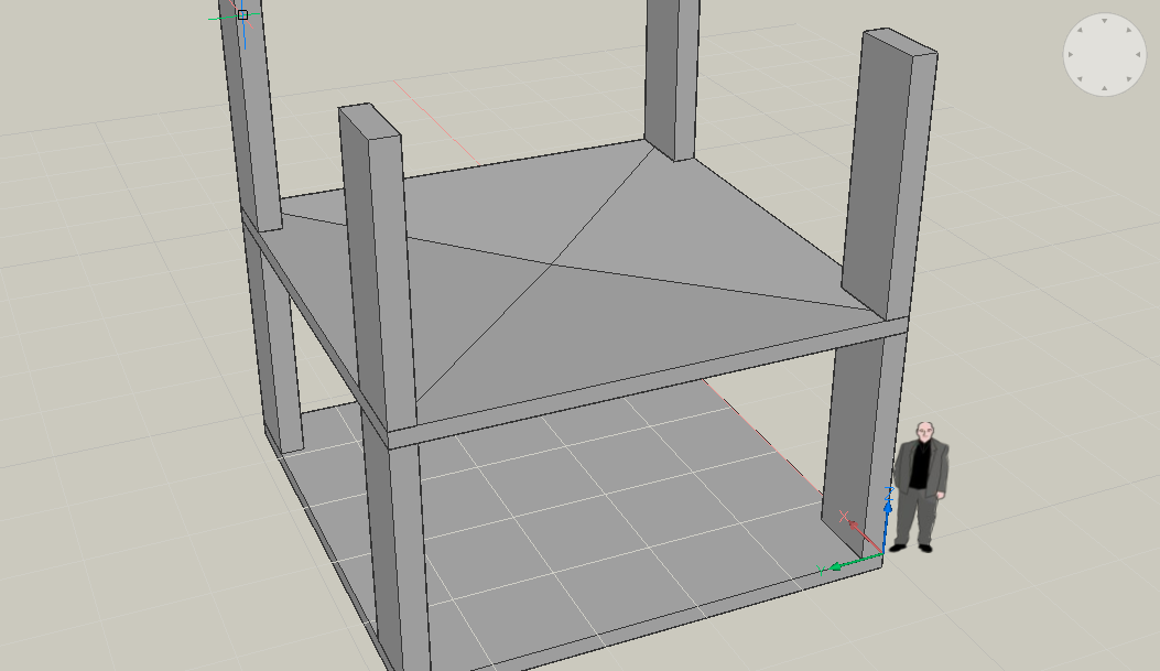
Using Shape, I’ve modeled a solid resembling what I’m looking for by subtracting an upside-down pyramid from a box solid. See attached image.
I can then select all the top faces and use the “move point” command to move the central vertex. It’s usable, but difficult to move the point in other than z-axis without directly typing in the displacement. I’m not seeing a way to add more vertex points to the solid. Any ideas?
Fast modeling of slab points is a critical feature for us, since slab grading is a big part of our work.
Comments
-
Do you mean the whole slab slopes. or underside level and top thickened to falls?
0 -
In V19 the _ConvToSolid command is indeed available. But there is also _ConvToMesh. So in theory you could convert to a mesh when you want to edit the grading and then back to a solid. Although that might not be ideal in a BIM context (loss of data).
It is also worth looking at parametric components with BC_SUBTRACT features. The feasibility of that solution would depend on the complexity of the required grading. But I can imagine that a small set of components (a wedge and 2 corner solutions) might already work.0 -
I use the "Manipulator"
Select a single Top or Bottom Face of a Slab to to make 1 side sloped.
Or, for both, choose the first Face.
(you can toggle between Faces by TAB key)
when you select the next Face, click a bit longer to make Manipulator
appear,
(or open it from Quad later)
drag it from is extra point, to set it to your desired rotation Axis,
hover over and click the desired Arc to start rotation.You can enter numeric angle values or snap to geometry to define the angle.
So 1 or both Faces will rotate and get your slope - but the side Faces
stay upright. Its top plan dimensions stay the same !This should also work for your invers pyramid.
Just rotate all 4 sides one after the other.0 -
@Tom Foster said:
Do you mean the whole slab slopes. or underside level and top thickened to falls?My example above has the underside flat, but sloping the whole slab is in many cases a requirement too. In 2D CAD sections, for a sloping slab of uniform thickness I usually use a filled multiline, justify from the top and simply add/remove vertices as required. If there were a way to give a mesh “thickness” while keeping vertices manipulable, it would essentially be the 3D version of this multiline technique.
0 -
Hover the top face of the freshly created slab and select the Extrude tool from the Quad.
Move the cursor slightly downward, 'into' the slab, the extrusion will start cutting away some thickness of the slab.
Now press the Tab key, which activates the Taper option, so instead of cutting away a slice of the slab, you now start cutting away a kind of inverted roof shape.
Two dynamic dimensions allow to either set the slope angle, or to set the 'depth' of the intrusion, which is probably what you want. Switching the input focus between dynamic dimensions is done by pressing the Tab key.So, now it is probably desired that this inverted roof has a single bottom point instead of a horizontal bottom edge?
This can be achieved by rotating the triangular faces a bit upward using the manipulator (not the trapezium-shape faces).Select a triangular face and place the manipulator origin in the middle of the triangle edge that coincides with the slab boundary, drag one of the spherical handles of the manipulator axes to make sure that this axis coincides with the 'fall' line of the triangle, by snapping to the lowest point of the triangle.
Now pick the desired rotation control to start rotating the face about the slab edge, and snap to the midpoint of the edge that you want to reduce to a point. Mind that if the rotation is not going in the desired direction, you may want to reorient the other manipulator axes using their spherical handle.
Repeat this process for the other triangular face to complete.
FYI: writing this description took ten times longer than the actual modeling did...
0 -
Thanks Michael and Hans,
These methods work, but they are not very user friendly, especially compared to SketchUp where it’s as simple as drawing lines to subdivide the slab faces, then dragging the vertices as required, or Revit where it’s a matter of adding a vertex to the slab, lifting or lowering while the program resolves the edges.
Ideally we would be able to grab a slab object, add/remove vertices, select individual vertices and see their x/y/z coordinates in properties to verify or modify them, or move them with their grip along ortho axes.
0 -
I would make up a list of taper angles corresponding to desired slopes, eg for 1 percent slope, the taper angle is 89.43. Using Hans' method, hover and extrude the top surface. When it's moving, type 'T' for taper and '89.43' for the angle. By moving the mouse you can make the pyramid pop up or push down into the slab.
0 -
I think mzarchtech not only wants to easily model such things but also
change them later also as easily.
Like you can do in a Mesh Modeling App.10 years ago Microstation's Push Pull Tool evolved to also Push Vertices
and Edges beside only Faces for Solids with its Parasolid Modeling Core.
Vectorworks uses the same Parasolid Core bur their Push Pull Tool is
still limited to Faces.
And as in Bricscad, there is also a similar tool to rotate Solids Faces.
After I got used to its strange workflow and have seen that it will also
get the same result, I would prefer to just rotate Faces 4 times for that
pyramid than missing a better tool.But there is always the option to send a Wish Service Request.
extending Push Pull functionality is always welcome.And currently there is also the option (commandline only) to switch
convert Solids to Meshes if that is more intuitive, and re-convert them
to Solids again when finished (which is a bit more tedious).0 -
@Michael Mayer said:> 10 years ago Microstation's Push Pull Tool evolved to also Push Vertices
and Edges beside only Faces for SolidsYes, I hope Brics gets that soon. I don't think Grips Editing will do that?
0 -
I think something like the Grip Editing would be a bit more user friendly.
Not sure.
Honestly I used MS edge or vertex mode very rarely. I always set it fix to
Face only Mode, as otherwise you can easily screw up your geometry.
Also Bricscad Developers may have much better ideas how to achieve
such features.0 -
It certainly would be useful to be able to work with vertices in the same manner as faces and edges. Doing this via grips seems logical to me.
Another way to form the sloped slab from an existing flat slab is:
- Draw LINEs diagonally across the face of the slab.
- Use the IMPRINT command to divide the face up along your lines.
- Using the QUAD, select any two opposing outside edges.
- From the QUAD, select DMMOVE and move the edges up.
You should find the outside edge of your slab moves up while the central vertice stays put. Having done this you would adjust the slab to the required thickness. This method uses a distance instead of an angle. It also allows you to use a point other than the geometric centre of the slab face.
Regards,
Jason Bourhill
CAD Concepts0 -
@mzarchtech said:
...for a sloping slab of uniform thickness I usually use a filled multiline, justify from the top and simply add/remove vertices as required.I would probably use the _PolySolid command instead.
0 -
It certainly would be useful to be able to work with vertices in the same manner as faces and edges
Hmmh,
when it works with Edges already,
why not cut a bit of the Pyramid's Pike (at the bottom in this case),
to get 4 Edges (+ rectangle Face),
so that you can grab the Edges to do your slope adjustments ....0 -
Assuming the floor slope is say 2 degrees...........
Selectionmodes is set to 2 (face)
dmExtrude
Select entities/subentities to extrude or set [MOde]: Pick the face
Select entities/subentities to extrude or set [MOde]: Enter
Specify height of extrusion or set [Auto/Create/Subtract/Unite/Both sides/Taper angle/set Direction/set Limit] : T
Specify taper angle value <0.0>: 88 (90 - the 2 degrees floor slope) Enter
Specify height of extrusion or set [Auto/Create/Subtract/Unite/Both sides/Taper angle/set Direction/set Limit] : (dragging the cursor into the slab) Enter(Same as Hans without the manipulator)
cheers
0 -
@Jason Bourhill said:
It certainly would be useful to be able to work with vertices in the same manner as faces and edges. Doing this via grips seems logical to me.Another way to form the sloped slab from an existing flat slab is:
- Draw LINEs diagonally across the face of the slab.
- Use the IMPRINT command to divide the face up along your lines.
- Using the QUAD, select any two opposing outside edges.
- From the QUAD, select DMMOVE and move the edges up.
You should find the outside edge of your slab moves up while the central vertice stays put. Having done this you would adjust the slab to the required thickness. This method uses a distance instead of an angle. It also allows you to use a point other than the geometric centre of the slab face.
Regards,
Jason Bourhill
CAD ConceptsThanks Jason, that's the closest workflow to what I'm looking for. We rarely define our slabs by slope or angle, it's typically the high points and low points defined, with the slopes varying between 1 and 5%.
Unfortunately the program creates some unnecessary "bulges" along the slab when the outside perimeter corners are manipulated, but otherwise the method is usable if we use DMMOVE on the internal vertices only.0 -
Here is a video demonstrating how to use IMPRINT in creating a sloped slab.
Creating a Sloped Slab using IMPRINTRegards,
Jason Bourhill
CAD ConceptsCome to the Australasia BricsCAD Conference
0 -
Yet another alternative is to create cross-sections of the desired slab along the diagonal, then repeatedly call LOFT to create the slab.
Creating a Sloped Slab using LOFTRegards,
Jason Bourhill
CAD ConceptsCome to the Australasia BricsCAD Conference
0 -
I find using IMPRINT with multiple entities tedious so I wrote the following LISP to reduce the number of prompts.
;------------------------------------------------------------------------------
; CAD Concepts
;
; QUICK IMPRINT
; Reduces prompting to IMPRINT multiple entities
;
; Copyright (C) 2019 CAD Concepts Limited.
;
; This program is free software: you can redistribute it and/or modify
; it under the terms of the GNU General Public License as published by
; the Free Software Foundation, either version 3 of the License, or
; (at your option) any later version.
;
; This program is distributed in the hope that it will be useful,
; but WITHOUT ANY WARRANTY; without even the implied warranty of
; MERCHANTABILITY or FITNESS FOR A PARTICULAR PURPOSE.  See the
; GNU General Public License for more details.
;
; You should have received a copy of the GNU General Public License
; along with this program.  If not, see <http://www.gnu.org/licenses/>.
;------------------------------------------------------------------------------
;
; File        : QuickImprint.lsp
; Author      : Jason Bourhill
; Web                   : http://www.cadconcepts.co.nz
; Date        : 08/01/2019
; CAD Ver(s)    : Bricscad
;
; PURPOSE:
; To quickly IMPRINT multiple entities onto an object
;
; USAGE:
; To load type (load "QuickImprint.lsp") from the command line
; or drag and drop the file onto your drawing using explorer.
;
; There is one command available:
;
; QUICKIMPRINT
;
;   COMMAND OPTIONS:
;   After select entities to imprint, you will be prompted as to whether
;   you want to delete or retain ALL the source imprint entities.
;
;------------------------------------------------------------------------------

(defun  C:QUICKIMPRINT ( / sset sset_imp DelSource)
 (acet-error-init  '(("CMDECHO" 0 ) 0 nil)) ; set error handler
 (princ "\nSelect a 3d solid, surface or region: ") ; prompt user
    (setq sset (ssget ":S" '((-4 . "<or")(0 . "3DSOLID")(0 . "SURFACE")(0 . "REGION")(-4 . "or>")))) ;  Filter selection to single 3d solid, surface or region.
    (Cond
        (sset
            (setq sset (ssname sset 0)) ; retrieve the selected entity to be imprinted
            (princ "\nSelect entities to imprint: ") ; prompt user
            (setq sset_imp (ssget))
            (cond
                (sset_imp
                    (initget "Yes No")
                    (setq DelSource (if (= "Yes" (getkword "\nDelete the source imprint objects [Yes/No] <No>: ")) "_Yes" "_No"))
                    (foreach ent (vle-selectionset->list sset_imp) ; for each of our imprint entities
                        (command "._IMPRINT" sset ent) ; imprint on our source object
                        (if (wcmatch (getvar "CMDNAMES") "IMPRINT")(command DelSource "")) ; IMPRINT remains active if sucessful, provide answer on whether to delete imprint object and end command
                    )
                )
                (T (princ "\nNo entities selected"))
            )
        )
        (T (princ "\nNo 3d solid, surface or region selected"))
    )
    (acet-error-restore) ; restore error
)
Regards,
Jason Bourhill
CAD ConceptsCome to the Australasia BricsCAD Conference
0


