IFC and Exchange Issues with Vectorworks

I have some Questions about my Data Exchange between Bricscad and Vectorworks.
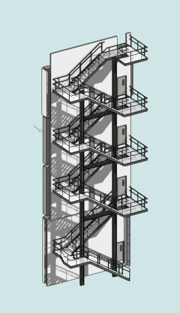
Example how it looks in Vectorworks
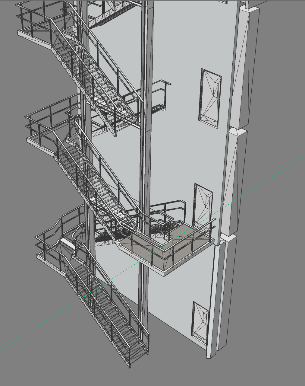
How it looks in Bricscad
Unfortunately I am not able to upload the DWG as it is 10+1 = 11 MB
but it is just the IFC imported.
Missing Parts
The right part of the stairs is manually modeled : Solids in a "Group", 1 for each Story.
When I apply a BIM Tag to the whole group only, Bricscad refuses to import.
Same when I apply additional BIM Tags to all Solids inside the Group.
Only the bottom "Balcony" came in, after I deleted the BIM Tag from the parent Group.
Attached is the IFC Import Log.
But when I reimport the IFC into Vectorworks, all Balconies come in and I assume
they would also appear in Solibri Model Checker.
Is this wanted behavior or just a translation issue ?Geometry Clean Up
The left Stair Part and Flights is created by Vectorworks Stair PlugIn Tool/Object.
Of course the Geometry is a terrible mess and so it looks quite bad in Bricscad.
But I will always get bad Geometries from Revit too.
How to deal with it ?
Comments
-
3.
AuditAudit does great things. But in my experience,
using standard Audit/Fix for the whole File,
makes file size smaller but basically by deleting half of my Geometry.
(likely that especially things like such Stairs my disappear completly)using AuditALL/Fix from within the Files,
freezes Bricscad after 30%using Quad Audit for the selection works reasonably fine
a)
Is there a way to let AUDIT fix what it can fix,
but preventing it from deleting things it doesn't like ?
(For manual attempts)b)
Aren't Commands like Audit, Simplify, .....
those rare CAD jobs that could be parallized for multi-threading ?
(It can take quite some time in my projects and I see only
1 core being used. (All MT flags ON)0 -
4.
The vertical Beams. (Columns, Members ?)What is the best way to "automatically" assign Profiles to it ?
I gave them an IFC Tag "IFC_Beam" in VW.
Could also use "IFC_Column".
They originated from any clients (imperial ?) Revit profile that I just
scaled to get kind of an "IPE 300" steal profile (or "HEB" nowadays)When I delete the imported BIM Beam Tag in Bricscad and try to
BIMCLASSIFY again from Bricscad to Member or Column,
Bricscad will not assign a Profile Definition.
I thought BIMCLASSIFY (Member or Column), or at least BIMIFY,
would do that automatically (?)What's the problem here ? The bad Geometry ?
Or the sloppy Profile that does not 100% match any real definition ?So far I was only able to manually assign Profiles, after complicated
Visibility and Selection actions.0 -
5.
Block Editing.When I want to get access to a Stair's crappy geometry,
I have to deal with "nested" Blocks.
In Vectorworks I double click the main Stair Block to go into
an Edit Mode, similar to Bricscad.
(But I can see and snap to (grayed+locked) Geometry outside of the Block, if I want)
Inside the Main Block exist further nested Blocks, like the Flight + its Railing
Block. In VW I can simply double click again a nested Block to go one step
deeper into the Edit Mode of that nested Block - and so on.So I can edit such a nested Block, the go out of its Edit Mode,
am still in Main Block Edit Mode and can switch directly to Edit Mode of another
child Block and so on.In Bricscad Block Edit instead, I have to leave overall edit Mode by saving
and start again by double clicking the Main Block - and search and select
my next Child Block from
an endless, non-hierarchical Text List from arbitrary named Blocks !
(Would be nice if Bricscad would allow me at least to hover my cursor over a
nested Child Block - and beside Main Block Edit Mode only, would also offer
an alternative to directly enter the "nested" Blocks Edit Mode)The old REFEDIT seems to do all that.*
So I do not really get for what is Block Edit for and why it is default ?
(And where Block Edit is heading at in the future ...)Or why RefEdit is called "Reference" Edit,
which makes me think about editing File References (?)EDIT :
- Refedit does allow to add other Objects and Blocks to be inccluded in
RefEdit Mode. But I can't edit other Blocks anyway !?
So what is the meaning of adding or plus/minus buttons in RefEdit's
temporary hovering Palette ?
Or what is its "RefEdit" Icon for ?
0 - Refedit does allow to add other Objects and Blocks to be inccluded in
-
6.
Shape 9,2 WIN- using standard Audit/Fix for the whole File,
makes file size smaller but basically by deleting half of my Geometry.
Just as an information to proof my thesis from #3.
Basically the same file as above, but the only AUDIT/FIX available in Shape,
will delete all Structural (crappy Geometry) Parts of my Stair.While Bricscad's AUDITALL,
but applied to the Stair Blocks only,
will repair fine - without deleting the Stringer Profiles ....0 - using standard Audit/Fix for the whole File,
-
7.
Crappy Geometry
DMSIMPLIFY in 2D ?Can I simplify that Region or Polysolid in Bricscad,
automatically or manually and get rid of the unnecessary
Vertices ?
a)
This was a Face extracted from an Outside Stringer of the Stair.
Those Stringers came in by IFC as (corrupt) Solids but e.g. PushPull
will fail.I can explode them,
delete 2/3 from the duplicate Faces at one of its ends,
(Whatever VW's Stair Tool forgot or made them for ...)
Stitch again,
to get a better Solid.
But DMSIMPLIFY will not get rid of the unwanted Stringer's top and bottom
Face Tesselation.
(Maybe because the whole Stribger's Top Surface isn't exactly planar).
PushPull will not help either to pull all Face Parts Level.That is why I thought of rebuilding the whole Stringer by extruding one of
its Side Faces. But as already the 2D "Profile" is crap, I will basically get the same
Solid result.
That is why I tried to "simplify" that Region or Polyline, to get rid of these extra Vewrtices,
but found no way to do so. Is there a way ?b)
Surprisingly, VW's Solid Stitching Command works very well for such Faces like
the exploded Stringer - as it is able to automatically delete such duplicated,
tripple end Faces at one side, when Stitching.
Bricscad's Stitch can not delete these. Therefore it will either answer with a
Surface or a Solid that won't work with PushPull anymore.Would it be possible for Bricscad to also add such an ignore and delete duplicate
Regions option - or even a function to automatically fill wholes to convert to
a real Volume Solid ?0 -
8.
Windows.I get VW Windows in by IFC, great !
I can even move them in a Wall and the cutout will follow, great !
(they have a BIM_SUBTRACT Volume)
No parametrics of course.
In fact "inserted" standard(!) Blocks.What gets lost is :
- the Sub-Layers used by Objects inside the Window Block and by Layer attributes
- Solid-ness. Although Surface's Regions are ok and STITCH without problems
I have 36 insertions of exactly the same Window.
For potential changes, all should change in exactly the same way.
Unfortunately, like in VW, I will get separate individual Blocks for each Window,
which prevents from editing all at once.
No problem in VW as they use a common "Window Style" for parametric editing.
But for working in BC, I have to do something.So I need something like :
a) Selecting all Windows of the same Size/Type - I found no way so far with Select Similar options.
b) Replacing all 35 Window Duplicate's Blocks by Block Window 1 - I found no way so far.What seems to work :
Although my imported Window Insertions are no Components but standard Blocks,
I can replace them by a real Component, like a BC library Window. (great!)
Unfortunately,
Bricscad's BIM world is Millimeter, VW's and my BIM world is Meter.
When I replace my VW Windows by a BC Component Window already in File,
it will replace by a Component Copy being 1000:1 off scale !?Seems like in the case of Component Replacement, the INSUNITS Conversion
is ignored (?)Attached a screenshot of such typical Windows Situations in my Projects.
The most right Window is an insertion of a real BC Window, adapted to match my imports.
The cleaner Window left to it a VW Window Block, which I stitched manually to Solids.
All others with its strange tesselation are VW Windows as they come in by IFC.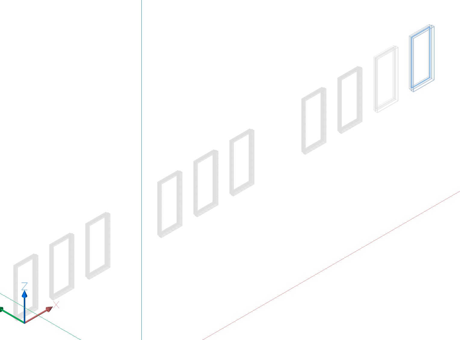 0
0 -
@Michael Mayer
These posts should probably be turned into Support Requests. I think very few BricsCAD users are dealing with a 'Vector Works to IFC to BricsCAD BIM' workflow. In fact there may be only one...Regarding the stringers in X_POLYLINE_TEST.dwg (issue #7):
The two stringers form a single solid yet the _Check option of the _SolidEdit command reports a single lump which is peculiar. And as you mention there are duplicate faces (triangular at the upper end). So obviously something is very wrong here.
You speak of unnecessary vertices, but the rectangular faces that form the top surface of the stringers are not co-planar. Which explains why _DmSimplify does not work. Maybe the decimal accuracy of the VW file or the VW IFC export is too low?0 -
Hi Roy,
yes, but before filing wishes and requests I would like some help
where I just do wrong. Or if there are completely different ideas
for better workflows.
Yes, the Stringers form a single Solid with 2 independent Volumes.So obviously something is very wrong here.
")
Yes, obviously the VW Stair (and other PIO) Tools Geometry is crap
from the beginning. That is true inside VW too.
It is clearly not Bricscasd fault that the geometry is bad.
Garbage in, garbage out.
But it is not so special VW Exchange problems. It is just an example.
I have more to do with Revit Exchange nowadays and its geometry
is even more crappier.
It is just that dealing with crappy import sources is a large part of
my work in general.Maybe the decimal accuracy of the VW file or the VW IFC export is too low?
I don't think it is the export.
It feels like some older parts of VW work with lower resolution in general.Yes, obviously the planar Faces aren't planar.
So DNSIMPLIFY works as expected.
It could just be a wish request, that their may be a tolarance settingso that
Simplify forces such anomalies to flatten (?)When I cleaned up, manually stitched to Solid,
I get a working Solid where PushPull works again.
Not sure for VW, but in Microstation, PushPull normally allowed to pull
such minimal non-planar Faces out - as it allowed to work beyond
neighboured Edges.
Bricscads PushPull seems a bit more limited or restrictive (?)
(I tried but Microstation doesn't like that special geometry either )2D.
But I was a bit surprised that I found no way to even delete any single Vertex
from a Polyline. Not sure if there really isn't a way or I just did not find it.
(In VW I would double click the Polygon for Edit Mode,
make a Marquee Selection around all unwanted Vertices and press DEL)Would it work for single deletions when I am in Vertex Mode of Edit Mode,
one by one. Or could I drag a single Vertex over on a neighboured Vertex
and Bricscad woudl weld them together ?
Or do Autocad users redraw their complex Polylines when they need to
adapt a Polyline's Vertex count ?0 -
If you align the UCS with a rectangular face at the lower end of a stringer and then _ID a vertex at the other end you will find a Z of 0.02, which is a huge tolerance considering drawing units are meters. I would say that the _DmSimplify command is not intended for this.
0 -
@Roy Klein Gebbinck said:
If you align the UCS with a rectangular face at the lower end of a stringer and then _ID a vertex at the other end you will find a Z of 0.02WTH
Another scale issue ?
When I draw a line from one to the other Stringer end,
it looks like only max 2 mm deviation.
(In fact it is something like a 0.000978 m)EDIT :
Your measurement could be possible if you have chosen one of those
Faces with the highest slope from average, to align your UCS.Yes, DMSIMPLIFY works well not deleting Edges when not planar.
But it could be quite useful with a tolerance, in some cases where such
slight inaccuracies just came by accident.0 -
Thanks for your patience Roy,
face at the lower end of a stringer and then _ID a vertex at the other end ...
That was a good idea.
PushPull in Bricscad isn't as restricting as I thought.
Like Push Pulling a Face frome one and to the height of the other end,
"can" work in some cases, over other edges, and cleaning the whole Face.Don't want to put too much effort in the Stringer Example though.
The geometry is really too bad in that case to invest.But maybe you can bring some light into :
2D.
But I was a bit surprised that I found no way to even delete any single Vertex
from a Polyline. Not sure if there really isn't a way or I just did not find it.
(In VW I would double click the Polygon for Edit Mode,
make a Marquee Selection around all unwanted Vertices and press DEL)Still no clue.
Would it work for single deletions when I am in Vertex Mode of Edit Mode,
one by one. Or could I drag a single Vertex over on a neighboured Vertex
and Bricscad woudl weld them together ?No, does not work.
Also dragging Vertices over each other, will keep the 27 Vertices for that Polyline.Or do Autocad users redraw their complex Polylines when they need to
adapt a Polyline's Vertex count ??
0 -
The _Overkill command can be used to optimize polylines.
0 -
Thanks Roy,
That was what I need.Overkill does delete/weld those extra Vertices that I dragged over other
Vertices. Unfortunately, even with high tolerances, I was not able to
simplyfy or reduce Vertices that are "nearly" planar.So if I draw a complex Polyline, like a Property Line, and need to change it,
there is no way to add or delete any vertices, (only moving).
And doing vertex count changes means either redrawing or to explode the
Polyline and deleting segment or drawing extra Lines and rejoining after ?0
