Coming from another CAD and stuck on something simple, move an object.

Hi,
I'm evaluating Bricscad for a possible move from another CAD package. I'm stuck on what seems should be a very simple task. I simply want to move an object ( entity ) to an absolute X,Y,Z coordinated. I have looked at the docs and video tutorials. They all seem to mention base point and displacement. From what I get out of this, base point is an anchor point and displacement is where you want to move from that point. An example, I draw a simple cylinder which is arbitrarily placed in space, I want to move it to an absolute coordinate of 0,0,0 on the WCS. I select the cylinder, set the base point to 0,0,0 and the displacement to 0,0,0, my cylinder does not move. I've tried other incarnations of selecting base point and displacement, and have only accidentally gotten what I wanted one or twice ( meaning I could not repeat the action ). I did see reference to using *x,y,z to place on the WCS and @x,y,z for a relative move, but nothing seems to work.
The other item is related to the handle point of an object, with a cylinder it seems to select the center by default ( at least on the face ), for a cube, it seems to want to select a corner. Is there a setting that makes the default handle the geometric center of an object?
What am I missing??
Thanks
Joel
Comments
-
When Dynamic dimensions (DYNMODE) are on coordinate entry switches to being relative by default (can be changed via DYNPICOORDS). You will see when Dynamic dimensions are on, that an @ is automatically prefixed to any coordinates that your type. If you want to enter an absolute coordinate, then you need to prefix your coordinate input with a #.
There are actually 3 prefixes that change the behaviour of coordinate input:
@ = Relative coordinate to the last point.
# = Absolute coordinate in the Current UCS.
* = Absolute coordinate in the World UCS.Regards,
Jason Bourhill
BricsCAD V20 Ultimate
CAD Concepts0 -
@Joel_l said:
The other item is related to the handle point of an object, with a cylinder it seems to select the center by default ( at least on the face ), for a cube, it seems to want to select a corner. Is there a setting that makes the default handle the geometric center of an object?Try using
GCENTERorZCENTERobject snapsRegards,
Jason Bourhill
BricsCAD V20 Ultimate
CAD Concepts0 -
@Jason Bourhill said:
When Dynamic dimensions (DYNMODE) are on coordinate entry switches to being relative by default (can be changed via DYNPICOORDS). You will see when Dynamic dimensions are on, that an @ is automatically prefixed to any coordinates that your type. If you want to enter an absolute coordinate, then you need to prefix your coordinate input with a #.There are actually 3 prefixes that change the behaviour of coordinate input:
@ = Relative coordinate to the last point.
# = Absolute coordinate in the Current UCS.
* = Absolute coordinate in the World UCS.Regards,
Jason Bourhill
BricsCAD V20 Ultimate
CAD ConceptsThat is the best explanation I heard so far, thanks Jason.
Unfortunately,
I am not able to input anything other than numbers into my DYNDIM
input fields !
(V20 on macOS, DYNDIM set to relative)And I can't see any prefixed @ anywhere in DYNDIMs or Command Bar.
0 -
Tried in Windows now.
Looks like it works for me - in Command Bar (only)
I mean, it also works in DYNDIM, just that there is no Visual Feedback
in DYNDIM, that it will work.And, you have to type all XY and Z values,
like "* 0, 0, 0"
I think it does not work by DYNDIMs in just one Axis.
Like locking a single Axis or for a single Axis Command like PushPull.
"* 0" will not work.So I have to try on macOS again that way.
(I think more and more, I should return to macOS and true macOS Apps)
0 -
I just tried this on my Mac and I can now position entities, Thanks!
I did go to snaps and cleared all but geometric center but it still seems to snap to the center of a face.. If I draw a cylinder, say 15mm diameter and 8mm tall, then select the center ( should be geometric center?? ) and move it to 0,0,0, the cylinder is placed on top of the Z plane instead of 4mm above and 4mm below. The center of the circle is on X=0 and Y=0 as expected.
new question,
I draw objects using top view and join, subtract... to get an object I want. I now change perspective to front view and want to draw some new shapes relative to that view. I thought maybe changing the UCS but what ever I try to draw still references the top view. What control am I looking for to change drawing orientation?
Thanks
Joel
0 -
- You have to set the UCS (user Coordinate System ) to the View you want to draw....
- UCS
Specify origin of UCS or [Face/NAmed/Entity/Previous/ View /X/Y/Z/Z Axis/Move/World] : v
Generally, if you want to draw in 3D, you have to set UCS first !
0 -
I just tried this on my Mac and I can now position entities, Thanks!
Me too now ...
I did go to snaps and cleared all but geometric center but it still seems to snap to the center of a face.
Same here.
I can deactivate snap to Face Center in 2D and 3D Snap Palette,
snap to Geometric Center on (in 2D snaps)
it will still snap to Face Centers (only).
(I'm on Mac again, a box, in 3D View)0 -
want to draw some new shapes relative to that view. I thought maybe changing the UCS but what ever I try to draw still references the top view.
For me it works when seting a UCS to Front.
Also when I have a suitable 3D Solids Face to grab the temporary Auto UCS
and pressing SHIFT to lock it.0 -
I now have everything sorted out except the snap to geometric center. I can place an entity where I want ( relative to center of face ) and draw on any view. The snap to geometric center is something I want to sort out. I can work around it by giving the Z offset when I move the part, or change the view and do a relative move only moving the needed axis.
Another operation I do is to import a PDF as an underlay and trace over items I want. I notice Bricscad does not have an autotrace function, but that's probably fine because they don't work well enough anyway. I hope it can extract objects from a vector PDF, off to try.
That's for the help so far. The not being able to place objects where I want them was a major obstacle.
Joel
0 -
sorted out except the snap to geometric center.
For me it looks like that function is for 2D elements only (?) ....
Seems to work for Polylines.(But I don't see any difference between Geometric vs Face Center snap though)
0 -
< geometric center> yes, I noticed that was listed under 2D also. There are some things I do that it is handy to have 0,0,0 at the geometric center of an object, but mostly because that is the way I have been doing things. Not a deal breaker.
I did try the PDF underlay and importing a vector PDF, both of those work fine.
So now I will just play more with 3D modeling and see how I like things compared to what I have now.
0 -
You can snap to Vector PDFs.
But I gave up as normally geometric resolution of PDF is so low
that you only get ugly numbers like 2.9999997 instead of 3.0.
So I went to a standard grid snap and deactivated PDF snapping.
I prefer to draw over PDFs from scratch.I hope it can extract objects from a vector PDF, off to try.
Therefore I think I never tried this.
I tried Tracing in other Apps a few times but the result always
caused more problems than it solved 0
0 -
@Joel_l said:
I now have everything sorted out except the snap to geometric centerThere is a centroid snap option is this add-on:
http://www.b-k-g.nl/bkg_additionalsnaps.html0 -
@Konstantin Sakellaris said:
the command PDFIMPORT could help !
A PDF file can be imported with ALL his components......
It could be a better "production line" for you than draw over them ?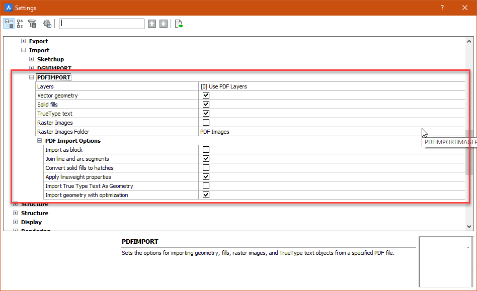
Yes, PDF import works fine with vector PDFs. I was able to lift the vector objects right out of the PDF. Works well.
0 -
@Roy Klein Gebbinck said:
@Joel_l said:
I now have everything sorted out except the snap to geometric centerThere is a centroid snap option is this add-on:
http://www.b-k-g.nl/bkg_additionalsnaps.htmlThanks, I will check it out.
Update: I did check it out, seems to work fine. Thanks again!
0


