Parametric loft

Hi, I'm attempting to model a parametric asymmetric pipe reduction.
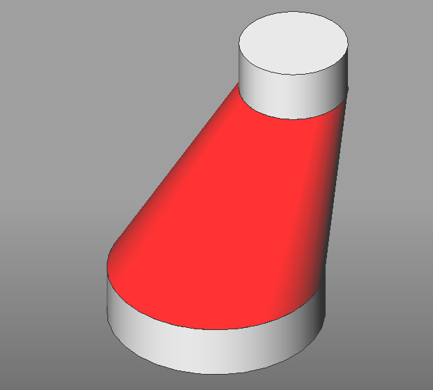
To make it simple the model is splitted in three solids: two cylinders and a lofted solid that should adapt to the two cylinders.
I can't find a way to parametrize the lofted geometry. Any idea?
Daniele
PS
Sorry for multiple post. Received a server error!
Comments
-
I think you will have to switch to a loft between two polygons.
0 -
Hi Daniele,
In what way would you like to parametrize the lofted geometry ?
You can easily variate the cylinder parameters by varying the radius, the position and distance of the centers
or by varying the loft parameters of the loft operation by scripting the command LOFT in Lisp or programming a routine in C#
or use 3D parameters .....
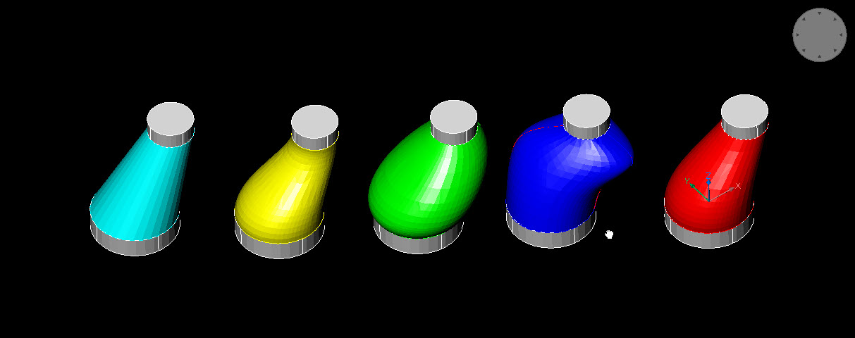
Here is an example of varying the loft parameters in the command line......
LOFT
Select cross sections in lofting order [MOde/selection options (?)]:
2 cross sections selected
Enter an option [Guides/Path/Cross sections only/Settings]
Current option is Smooth. Enter an option [Ruled/Smooth fit/Normal to/Draft angles/eXit]
Current option is Smooth. Enter an option [Ruled/Smooth fit/Normal to/Draft angles/eXit]
Current option is Smooth. Enter an option [Ruled/Smooth fit/Normal to/Draft angles/eXit] :r
Current option is Ruled. Enter an option [Ruled/Smooth fit/Normal to/Draft angles/eXit] :d
Current option is Draft. Specify [1A to start angle/1M to start magnitude/2A to end angle/2M to end magnitude/eXit] :
Current option is Draft. Enter an option [Ruled/Smooth fit/Normal to/Draft angles/eXit] :n
Current option is Draft. Specify normal to [Start/End/Both/All/eXit] :b
Current option is Normal(Both). Specify normal to [Start/End/Both/All/eXit] :
Current option is Normal(Both). Enter an option [Ruled/Smooth fit/Normal to/Draft angles/eXit] :d
Current option is Draft. Specify [1A to start angle/1M to start magnitude/2A to end angle/2M to end magnitude/eXit] :1m
Enter the start magnitude <0.000000>: 0.5
Current option is Draft. Specify [1A to start angle/1M to start magnitude/2A to end angle/2M to end magnitude/eXit] :1m
Enter the start magnitude <0.500000>: 0.05
Current option is Draft. Specify [1A to start angle/1M to start magnitude/2A to end angle/2M to end magnitude/eXit] :
Current option is Draft. Enter an option [Ruled/Smooth fit/Normal to/Draft angles/eXit] :n
Current option is Draft. Specify normal to [Start/End/Both/All/eXit]
Current option is Normal(Start). Specify normal to [Start/End/Both/All/eXit]Cyan option **Cross sections only** Yellow option **Normal(Both)** Green option **Draft angles** , 1A to start angle , 45 ,2A to end angle , 45 Blue option **Guides ** using the 2 red curves as guides for lofting..... RED option **Normal** , normal to End
 0
0 -
Hi Konstantin, I'm using the standard BricsCAD parametric engine. This way no code is required. Unfortunately it seems a limit of V20. I made few tests using the polygon as @Roy Klein Gebbinck suggested but it requires a large number of parameters and still not very stable.
0 -
Hi Daniele, yes i find the parametric engine for this task rather overdimensioned and not explicit.....
I would rather write a script or code.0 -
Hi Konstantin, I need to create a "self contained" component. Need to teach BricsCAD users how to create their own library items. I can't write code here. Hope the V21 engine will improve!
0

