How to generate simplified drawings

Even in Model View sections I get distracted by the hatches
on cutting faces.
I would be more interested in a simplified drawing Style.
Here a few examples of what I am looking for :
https://www.homecrux.com/wp-content/gallery/north-star-apartment-by-nice-architects/north-star-apartment-by-nice-architects-5.jpg
http://1.bp.blogspot.com/_E-U7KDrvlEE/R6hCxljQi9I/AAAAAAAAAHY/PH7gEuc61ec/s320/fpt_0058-02.gif
https://i.pinimg.com/originals/b3/70/52/b37052316d5138bc468a44a101fdbedb.jpg
https://cdn.architecturelab.net/wp-content/uploads/2014/02/sectionA.jpg
What is the best approach ?
Are there any other Ideas than using fake/presentation Building Materials
in temporary Compositions ?
Comments
-
@Michael Mayer said:
I would be more interested in a simplified drawing Style.YES!! Good examples.
Moments ago I was navigating yet again to find where in the twelfth nested level of support folder hell hides that _SectionSettings.dwg that promises—somehow—to hold the key to nice looking drawing output. I started to fiddle for the umpteenth time in vain to achieve what I want with the various layer naming, colors, linetypes, lineweights, text styles, block symbol, scale defaults, etc. I tried to compare the template Section Plane settings with those of an ad hoc section in a recent dwg that had come close, but the drawing explorer window doesn't show the two side by side (like the very handy way it does for editing dim styles), nor does it preserve which zones I collapse because the list doesn't fit on my screen without having to scroll. After a bit of toggling back and forth, it gave me the "application became unstable" warning, so I gave up and checked in here before restarting.
For schematic design, I also resorted to a "fake" monolithic material composition. In the next phases of design especially, it would be a shame not to take advantage of BIM compositions, but I still want graphic output I can readily control. BricsCAD is so amazing at the rest of what it can do. It should not be so difficult to generate legible and aesthetic drawings!
0 -
@Michael Mayer said:
I was navigating yet again to find where in the twelfth nested level of support folder hell hides ....Are you using the old offline Help chm? I've got used to the online Menu bar>Help>Help Help (don't panic - false alarm!) - any old search term usually gets there first go.
0 -
In Vectorworks I have that in Viewport Settings.
If the Cut Face appears as separate Plies of Compositions or
as a uni color of choice.
Also Model Space has a switch between detailed and simplified
representation. (And now 3 levels of detail which can hide
geometry applied to higher LODs)
The rest, if Hatch, Material or Color is controlled by Attributes
or by Classes.Basically in VW I also work with "fake" monolithic material compositions.
But there it is easier to keep mitered Wall Connections and expansion
directions when replacing final Compositions.I assume, so far, Bricscad does not generate Areas/Regions of the
Cut Faces, where they could fill in a color and add weighted lines
around (?)But I will question if activated standard Sections in Model Space
should show a Hatch at all or better just the Solids Face Color.
At least for View Window LOD ON/OFF.For now the generated Sections and Plans look pretty hard to read
and show more complexity than the Information I feeded into my
Model so far.But maybe I am doing wrong.
For now I just don't oversee from where to approach a simplification.
From Building Material side, from Viewports or from Section Styles.0 -
But what I really would like to have for low LOD Sections
is that only Elements/Plies with "Structural" Tags
get full Color tint,
while secundary Plies like Insulations and (soft) Claddings
may stay white and keep their fine Outlines.Something where Vectorworks in simplified Section Area
would just fill everything.0 -
Could we have facility to make up our own rule sets? called LODs if you like but that means something specific in CAD nowadays. Two or three different setups that I'd standardise on, prob different from anyone else's.
0 -
Well in VW we got just 3 LODs to switch.
You decide for any Element on which, all or not LOD they will be visible.
So everyone can set Objects it as he/she likes.Imagine a Symbol (ACAD=Block) of a wash basin,
where the 2D lines and curve will reduce when lowering LOD,
until in lowest LOD you will only see the Outline of it.Just the PIOs (Plugin Objects) use their pre-defined output,
which e.g. for Windows and Doors does seem to not meet everyones taste so far ....0 -
@Tom Foster said:
Are you using the old offline Help chm? I've got used to the online Menu bar>Help>Help Help (don't panic - false alarm!) - any old search term usually gets there first go.My comment was not about finding the topic in online help (although pointers from forum folks are invaluable for learning where to look), but rather about the depth in which the BIMsection settings themselves are buried, at least on Windows systems.
The fifteen section-related files are nested eleven tiers deep: C:\Users\username\AppData\Roaming\Bricsys\BricsCAD\V20x64\en_US\Support\Bim
right there near other support files such as default.pgp.
But not everything lives in that neighborhood. Model, sheet, and sheetset template files are in a parallel tier, over in .\AppData\Local...
Meanwhile, components and render materials hide out way over in C:\ProgramData\Bricsys
I don't remember where BIM compositions reside.The point is, it's a lot to wade through when attempting to adjust the output of 3D-to-2D translation to something workable, let alone fine tuning it.
Many of the default template files are interdependent, thus the solution is not a simple matter of pointing SRCHPATH and other support folder paths to our own custom templates, blocks, and other shared resources. Such customizations should be easy to incorporate. However, in my experience so far, modifying the wrong combination wrecks havoc. For example, a missing sheetset template causes BimSectionUpdate to fail (see also https://forum.bricsys.com/discussion/36015 or https://forum.bricsys.com/discussion/35694), or section tags turn up oversized (cf https://forum.bricsys.com/discussion/35821) or upside down, etc.
Because of this, I am wary of modifying the numerous default templates and support files, even having backed them up, of course. And also because, within our own practice, we want to be able to apply different settings for different scenarios, exactly as Tom says:
@Tom Foster said:
Could we have facility to make up our own rule sets? called LODs if you like but that means something specific in CAD nowadays. Two or three different setups that I'd standardise on, prob different from anyone else's.0 -
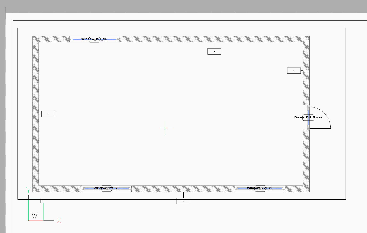
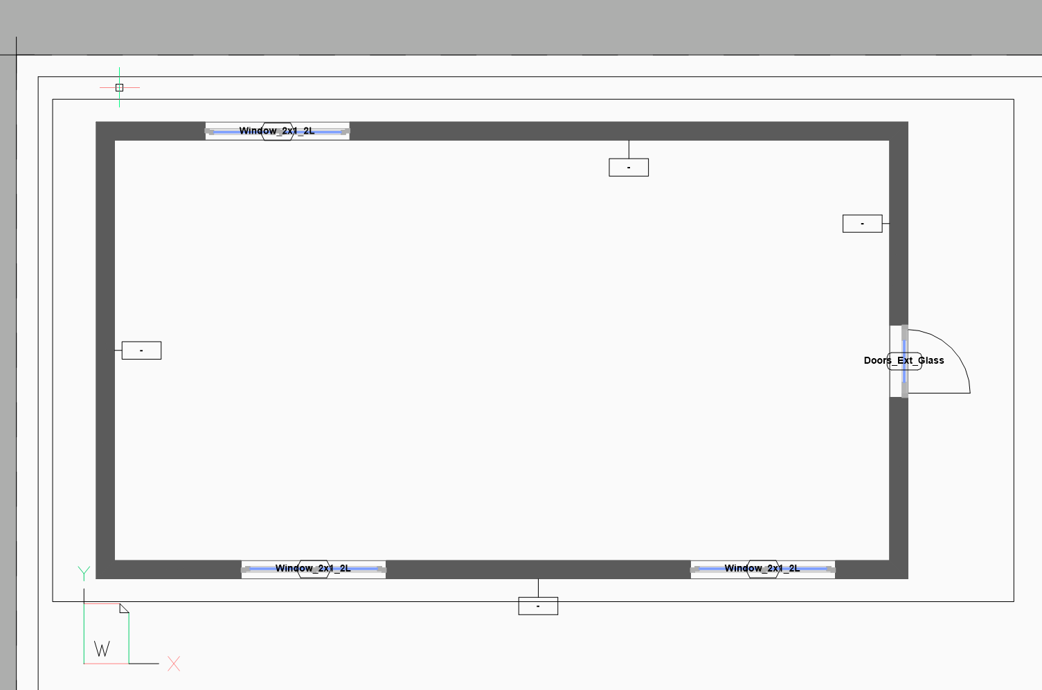
Hey, I also tried find some way to do this. It can be done easily if no compositions are applied - see screens. Only one setting in the section plane setting to set solid fill for all sectioned objects. You can change color, layer and other setting. Works fine.
But You cannot use this way, when composition is applied to wall. Then it always hatch according to plies in composition.
So my workaround is to save copy of file, remove compositions from model and export like in the screenshots.
But I only need this simplified drawings in the first phases, so does not bother me much. I apply compositions in later phase when detailed view is needed.
Hope it helps someone ;-)

 0
0 -
This is what I want to look like my generated drawings :
 https://www.youtube.com/watch?v=24rnfO8s0hU
+
According to local drawing standards,
e.g. for a Plan Drawing,
I need an upper and lower plane to define what Objects
are included in a secondary fashion.E.g. important objects, like Windows, above Cut Plane,
have to appear in dashed Lines !
Everything important below, hidden by a Slab or such,
like Foundations, have to appear in dotted lines.0 -
Great video - I agree entirely that's the look we're after in building incl CAD , but sadly few CAD draftspeople do that, probably because CAD isn't set up to do it, so it's arduous to achieve, though not bad once systems and routines are in place. Consequently, even to a practiced eye, I find many CAD drawings for building very hard and ambiguous to interpret - shudder to think what they make of it on site.
BTW, the guy's insistence on crossing lines at corners is a red herring - not necessary, just his artistic style. And he clearly is art-school artistic, which I am certainly not, but that doesn't prevent creation of great buildings and production of clear illustrative and technical drawings, like his.
Still not being fluent with 3D, not using all the facilities like sections, I am a bit horrified and incredulous to read here that the visual output isn't readily customisable, even in the cumbersome way of render materials. CAD developers always claim that they keep in close touch with users, to understand their practices and needs, but things like this make you wonder just what kind of architects and draftspeople they do consult - none that I'd wish to employ, anyway! (not that I employ anyone - previous attempts creating more work and stress for me, rather than less). More it seems that developers sit in their ivory towers and imagine what they think industry practice might be - or what it should be, as there's a lot of ideology there, like the notion that 3D will or should entirely replace 2D 'drawings'.
0 -
On another point, in Michael's OP, https://i.pinimg.com/originals/b3/70/52/b37052316d5138bc468a44a101fdbedb.jpg - what's going on there? No less that 15 section lines, front to back. 5x more than you'd ever consider necessary to illustrate a scheme, so what's the thinking - it it just so that large scale construction details can be taken off on that no of cut planes?
0 -
For me it looks like has has only 3 Sections
(called x,y and z with the black stripes)Numbers and Letters for me look like Axes - for each building element ?
0 -
Nevertheless,
I played with some project exports in Bricscad,
set some Sections and let Bricscad render Plans.And it is ... ähm ... an other Drawing Style than I am asking here for.
And I still don't like the noisy Hatches in sectioned areas,
neither live in Drawing Window nor in Viewports.
I would prefer a Solid Fill.0 -
@Tom Foster said:
BTW, the guy's insistence on crossing lines at corners is a red herring - not necessary, just his artistic style.Exactly what I did in my Studies.
I found it great at that times.
My Professors found it .... red herring ....0 -
Most of my drawing are complex, with many layers. So, if I were to create a drawing with the kind of finesse he includes, I would wait until the design were truely finished. Then, I would create copies of the drawings, so that each version can really be edited to be what I want it to be. Trying to do the sort of features he shows with a physical drawing onto a CAD drawing is quite difficult to do otherwise. Somethings, such as a drawing of a door hinge on a large wood garage door, need one level of detail when you are close, and a different level, or even removed from a more distant view.
But, in reality, just what the standard CAD file creates is nearly universally accepted, even if it is far from ideal.
-Joe
0 -
I am not sure if I got this right,
but new "Drawing Customization" in V21 could be the solution to
create cute simple drawings ?https://fast.wistia.net/embed/channel/s1t99s07d0?wchannelid=s1t99s07d0&wmediaid=nwimm8qcpn
I haven't fully watched the video so far and may need to watch it another 5 times
to understand. It looks a bit too complicated to just start playing from the new Palette.
Not that self-explanatory but maybe very universal and capable.0 -
Nah, I am not really sure.
Looks like "Drawing Customization" is more suited to a few special Plan Sytles.
Like e.g that Fire Rating.Otherwise you may get mad when filtering searching through all Entity Types ...
but who knows.I looks like basically I could get that 30x40 look, from the video above, just
by setting Section Planes in Drawing Manager. (all 4 Options)
That seems to work for Generated Sections.It will not work for me for Clipping Sections in OpenGL View though.
I never manage to bring my true Section Fills as there still seem Z-fight
overlapping coplanar Surfaces that use Entity Attributes.Also there is the problem that you always need to select all Section Entities
when setting up or doing changes to Section Planes.
And worse, when creating a new Section, it will fall back to any arbitrary
Bricscad Default with Hatches (non-Solid)So I think we would need Section Styles.
0 -
Hi Michael,
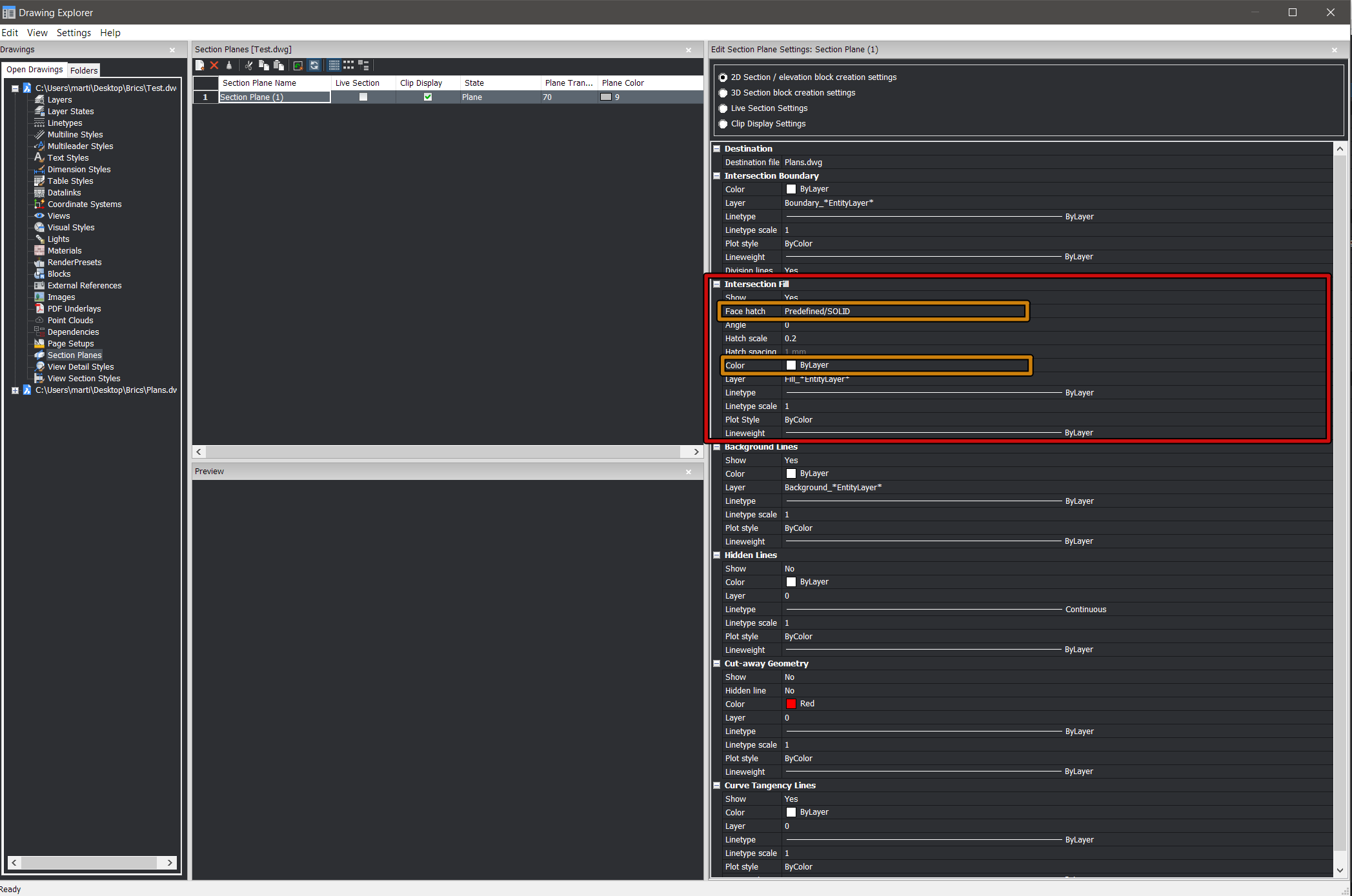
I think drawing customizations is worth trying for this. It is devised as a very general customization tool for generated drawings that you can use for your own purposes. Even for some minimal deviations from the default result, such as making all walls appear solid irrespective of their composition in the BIM model. You only need to specify the overrides in the customization and do not have to specify the appearance of all entities. Everything indicated as having "Default" style in the customization or anything not mentioned in the customization, will adopt the default behavior as specified in section settings and section plane settings.
As a quick start guide, I attached a recording in which I define a drawing customization to just make all walls appear solid when sectioned and then I apply it to a simple demo model. To override the appearance of walls, I add one rule to filter on walls using the BIM Type property. Then I define an entity customization to apply to those walls. It simply draws all the geometry of the walls in a dark grey color and overrides the hatches of the plies with a single solid material. This material is stored in the customization itself and does not affect anything other than the drawing result (i.e. does not change the 3D model or quantity take-offs etc.)
Customizations are project independent, so you can reuse them on all your projects. They are stored in a subfolder "Customizations" in the folder specified by the setting "Section settings search path". So you do not need to re-do this configuration on every file or section plane.
BTW, if you want to apply some customization to everything in the model, and thus mimic the use of section plane settings which are not entity specific, just make a rule without a filter or a filter that accepts everything.Note that, for now, you can only specify customizations on viewports that were defined by the use of the project browser.
Hope this helps a bit,
Jürgen
0 -
@JurgenDZ
This does look promising! Thank you for the quick start lesson. Very helpful.Customizations are project independent, so you can reuse them on all your projects.
Excellent. And the ability to apply different customizations to different drawings even within the same project overcomes what had been a puzzling flaw in the section settings system.
0 -
Thank you JurgenDZ,
yes, to know that Drawing Customization is also meant for overall
Drawing/Office Style customization and your Video, really helps.
I should look deeper into it.I still think such a Customization can get pretty complex pretty fast.
e.g. the Wall example will also need to apply to things like Columns, Slabs, ...
and you may also need to customize Windows, Doors, Components, ...
in detail.0 -
I still think such a Customization can get pretty complex pretty fast.
e.g. the Wall example will also need to apply to things like Columns, Slabs, ...
and you may also need to customize Windows, Doors, Components, ...
in detail.That's true, but I think you can gradually build up your customization and once ready, you don't have to do it again. Note that you can also reuse your entity customizations in different rules. E.g. the "solid" customization could be re-used for columns, slabs,...
Anyway, let us know what your findings are. We consider this a first iteration of this functionality, so your feedback is very relevant for future development.
0 -
For now I see the problem for Windows, that you may want solid Frames
but not for the Glass Pane. For Doors similar but not exactly the same.
All are Solids and you may go down into layers (?)Or if you want your texts in red, like in the example Video (at about 10:00).
You realize how long the list of Entity Types in Bricscad is.
And I need to filter not only for Text, but also Dimension, Annotation,
Tags, Markers, .... or even things I never heard before and didn't know existed.If I compare Drawing Customization in Bricscad with Vectorworks,
it seems to be a large part of VW's Viewport Settings AND VW's Data Visualization
all in oneAnd I am a bit confused by the UI so far. Where I activate a Filter
or a Customization, at which depth of the dialog I currently am and such.
I always want to click on the image in dialog but was meant to click the
plus sign at the bottom. It is all pretty abstract for me.But have to play and get used to it.
0 -
I searched and played and I think I learned a bit.
Section Planes.
Looks like new Section Planes get their Settings from User Settings Folder.
Which could point to another location - so could be a "Workgroup" or Office Standard Folder.
A *.dwt is a DraWingTemplate while a *.dst is a Dr...ahm....Section Template.
Not sure how but it looks like I could set suitable Section Settings by adapting Section Templates.Drawing Customizations.
I managed to get @JurgenDZ results, thanks of his Video and some optimistic plan-less modifications.
Pretty unlikely that I could repeat this again tomorrow or in a few weeks though.I think I would need to see the whole Tree and Hierarchy of Drawing Customization like Structure Browser,
to not get lost in abstraction, by seeing the whole Customization Structure in front of me and be able to use
it for Selection and Navigation.
(Drawing Customization "Properties" on the right docked multi Palette, opens DC Structure Tree at the
left docked "Structure" Palette)
Also I wouldn't have expected that I also need Building Materials.0 -
@Michael Mayer said:
For now I see the problem for Windows, that you may want solid Frames
but not for the Glass Pane. For Doors similar but not exactly the same.
All are Solids and you may go down into layers (?)You are right about this. Right now, it is not possible to customize subentities of a window separately. We are thinking about solutions for this.
Or if you want your texts in red, like in the example Video (at about 10:00).
You realize how long the list of Entity Types in Bricscad is.
And I need to filter not only for Text, but also Dimension, Annotation,
Tags, Markers, .... or even things I never heard before and didn't know existed.I do not really understand this. Maybe there is a misunderstanding. The rules in the drawing customization work on entities in the 3D bim model during the process in which they are being sectioned and projected on a sheet view. Tags, annotations etc. reside on the result sheet and are not affected by drawing customizations as it is conceived right now.
I managed to get @JurgenDZ results, thanks of his Video and some optimistic plan-less modifications.
Pretty unlikely that I could repeat this again tomorrow or in a few weeks though.I think I would need to see the whole Tree and Hierarchy of Drawing Customization like Structure Browser,
to not get lost in abstraction, by seeing the whole Customization Structure in front of me and be able to use
it for Selection and Navigation.
(Drawing Customization "Properties" on the right docked multi Palette, opens DC Structure Tree at the
left docked "Structure" Palette)
Also I wouldn't have expected that I also need Building Materials.Thanks a lot for this feedback on the UI. I think I see your points. We will collect feedback from other users as well and try to improve on it.
0 -
@JurgenDZ said:
You are right about this. Right now, it is not possible to customize subentities of a window separately. We are thinking about solutions for this.
Maybe not the highest priority and most urgent but
I think it could be interesting. Thanks.I do not really understand this. Maybe there is a misunderstanding. The rules in the drawing customization work on entities in the 3D bim model during the process in which they are being sectioned and projected on a sheet view. Tags, annotations etc. reside on the result sheet and are not affected by drawing customizations as it is conceived right now.
Ahm, I don't often have to deal with 2D and Plans, am not very experienced in 2D.
I didn't mean the Paperspace>Viewport>Annotation Space content.
I meant the generated Texts and its Frame borders.
Like Windows and Door Labels, Room/Space Labels (Raumstempel here)I think it is unlikely that I will get all by simply filtering for "text".
And I may not even know the names of all related entity types that I would have to search/filter for.Thanks a lot for this feedback on the UI. I think I see your points. We will collect feedback from other users as well and try to improve on it.
I am a bit overwhelmed, but also pretty excited about the new Drawing Customization Feature.
As I think it could make generated drawings better looking, better legible and maybe better
fit local drawings standards. Like german DIN Drawing Standards, which may be one of the
strictest example out there.
Related to Drawing Customization would be things like line weights, line types, Hatches and
such things, also depending on drawing scale[OT]
While other Scale Dependency might be more related to Building Elements and Components
and their 2D representation.
Or in Section Generation itself. Like the need to show related but occluded Elements like
Wall openings, Windows, Beams, Roof openings, ....- When located above cutting plane in dotted lines
- When located below cutting plane in dashed lines
Where a true Top Plan Section may need a Volume above, to know which of non-cut Elements
need to be included, plus a similar Volume below, beside an infinite or limited View Depth to
show extending non occluded building parts of lower Stories.
Examples would be 1:50 scale Elevations that show Wall thickness and Slab locations in
dashed lines (behind) or Floor Plans that show Beams or Girders in dotted lines (above)
[/OT]
Maybe Drawing Customizations should also include Layer Sets (?)
Like a Plan Customization with Visibilities optimized for the needs of an electrician vs, another
Customization optimized with colored Spaces and Furniture for the client and such things.I think it would be very nice if Bricscad could deliver some sample Drawing Customizations
examples of a smaller test project.
(I think the older Villa project would be better suited than the current new demo Villa, as it is
already quite large and complex)
Or even better by providing localized Drawing Customization Versions compliant with
local codes at one point.
(I vote for a common single EU code drawing standard)Just my thoughts.
0 -
@Michael Mayer said:
show related but occluded Elements like
Wall openings, Windows, Beams, Roof openings, ....- When located above cutting plane in dotted lines
- When located below cutting plane in dashed lines
and following items - a 25yr dream coming true at last!
When I bought BricsWork 1995 (immediately became Bentley Triforma) I imagined all that would be part of it. No such luck, or even users' support and interest, or developers' understanding of what might be - until now, it seems! Holding my breath, and leaving exploration of same to the BIM-fluent, while I work on in 2D as ever.
0 -
I am a bit unfair,
@Owen Wengerd gave me his small finger and I took the whole hand ...I started the Thread with nice, simplified Drawings and went into generated Drawings
applying to complex local Drawings Standards.
On the other hand, if there is any company that I trust to get near to that target,
it is Bricsys.Bentley Triforma for me was at a very basic level of what we call BIM today.
It was fun but just bad implemented in the usual Microstation 3D environment and
you never knew where to run into a dead end street. Mainly just because of Microstation's
complicated Workspace/User/Project settings.
But there were far worse BIM vertical applications available which just limited Microstation's
3D capabilities. Forgot the name, Speedi.... ?In 2010, as switched to Mac 3 years before, I started looking for CAD alternatives to Microstation,
in general, as I quitted my support contract years ago and in special for Apple OS X support.
I looked quite depply into Demo versions and I was really impressed by Archicad demo at that
time in this regard. (Allplan was quite nice also, but Windows only)
At that time, for me it looked like Archicad's generated Plans from 3D model are already useable.
They also had kind of different Drawing Customization Sets, to generate Plans for protectants,
approval, presentation, ...
For me Archicad is still the standard for architectural-only BIM usage. (It has other flaws though)
Maybe also Revit.But Bricscad's Drawing Customization, for me, already goes in this direction and maybe can solve
many problems, if they approach with their "new school" technologies.
Mainly AI and maybe ML could spread generated Labels in the most aesthetic and useful way
in our drawings at one day too.TL;DR;
I think Drawing Customizations are a very cool Feature.
So far not user very friendly for me, but much more capable that previous Section Settings.
(which I now understand much better too)
I think they can already answer the initial question of this thread,
how to generate nice simplified drawings.0 -
@Michael Mayer said:
I think it would be very nice if Bricscad could deliver some sample Drawing Customizations
examples of a smaller test project.The documentation for drawing customizations is under construction as we speak and some example customizations will be distributed as well.
TL;DR;
I think Drawing Customizations are a very cool Feature.
So far not user very friendly, but very and much more capable that previous Section Settings.
(which I now understand much better to)
I think they can already answer the initial question of this thread,
how to generate nice simplified drawings.Happy to read that!
0


