2D : Rectangle (?)
Comments
-
Yes, all cad illogic was originally created by Autodesk, and Brics has to follow suit so as not to frighten away the longtime AC users.
Mark the origin with something so you'll know where it is. Then select an entity, issue the Move command, and press Enter or space bar instead of picking the base point. You'll see the rubber band displacement vector originating at the origin. Cool?
0 -
In regards to the why question, I had a chance to use a another program from the time before AutoCAD became available. It is Medusa. And they show a lot of similarities. Blipmode, which put little squares wherever you clicked, and absolute coordinates we're just typical of that day.
-joe0 -
I remember reading that Mike Riddle was a cad operator before he wrote Autocad. Maybe he used Medusa.
VectorWorks started just 3 years after Autocad, with a completely different approach. But it only ran on the Mac, and there was no PC version until Windows 95. By then AC had a virtual monopoly, and its users were afraid to try anything different.
Medusa is apparently still in business. They offer a free cad program too.
0 -
@Anthony Apostolaros said:
Then select an entity, issue the Move command, and press Enter or space bar instead of picking the base point. You'll see the rubber band displacement vector originating at the origin. Cool?I could replicate it with the move tool.
But not with Rectangles or lines.0 -
@Michael Mayer said:
But I am happy that also BC recently learned that you can snap the origin symbol.Unfortunately not
(at least in BC/Shape 18 on Mac)0 -
-
Some commands (_Move, _Copy) have a default _Displacement option and default command options can be selected by hitting Enter. You could say that in these cases 'Enter means 0,0', but I would not as it can only lead to confusion.
0 -
Got it,
like accepting a Polysolid's default height by a RMB click ...0 -
@Michael Mayer said:
One other thing about reactivating a Tool.
I think I could live with a RMB click.It is already there !
It works by a "loooooong" RMB Click.(I personally would prefer the Long-RMB-Click for the "neutral Quad"
and the Short-RMB-Click for repeating Tools)0 -
Small hijack... Can one start a rectangle from it's centerpoint?
0 -
Yes Via a lisp etc.
0 -
Below is a comment, I had apparently typed some months ago. But, for some reason it was never posted, and stayed stored
The other issue with VectorWorks is that it didn't have the precision of AutoCAD. If they had come out with a PC version, and then Windows early on, they would have had a greater chance. But in those early days, it was not clear who would win the personal computer wars. In the end, the open architecture of the IBMs architecture, and all the low-cost clones is what made them the standard.
Autodesk also worked hard to prevent the low-cost CAD programs from working with the DWG format, until eventually loosing in the courts. I wonder how those things may have played out if they didn't have a virtual monopoly in the PC world for so many years. Vectorworks was certainly a contender.
0 -
Upon re-reading the thread, I am surprised that a parametric rectangle wasn't suggested. It would be inserted and then edited like other parametric objects. A different version one could be created that had a center point. A simple macro button could be created to automatically insert the parametric rectangle as a block that it explodes, or kept as a parametric block.
-Joe
0 -
If BricsCAD has constraints then something like this should work.
https://blogs.autodesk.com/autocad/autocad-rectangle-constraints-tuesday-tips-heidi/
0 -
Another way to get that ability to drag one corner of a rectangle while keeping it as a rectangle would be with a lisp-based custom command. The user would start by picking a corner of a rectangle, and the function would then check to make sure the pick found a vertex of a polyline with 4 right angles. If so, it would start rubber-banding a rectangle using the opposite corner of the selected polyline as the base point. After a second pick point, the function would move three of the vertices so that the selected polyline is now a rectangle defined by the rubber-banding.
0 -
Nice idea Anthony 4 points at 90 corners, BUT rotate to 30 degrees. Drag a corner. not a simple +/- X Y any more. Yes a lisp I dont have it but guess it exists.
Ok use UCS OB then +/- x y
0 -
@ALANH said:
..... Yes a lisp I don't have it but guess it exists. .....I don't think it does exist. I've searched for it but didn't find anything. I thought about writing one myself, but I'm very slow at lisp coding and it would take me several days. There are people on this forum who could do it in a few minutes.
Most people in DWG-world have never seen that type of manipulation of rectangles. Rectangular viewports can be drag-re-sized and re-shaped while still keeping them as rectangles, but maybe no one's made the mental leap from that to rectangular polylines.
Vectorworks' true rectangles can be manipulated just like BC viewports. When I worked in VW I used that all the time. I think corner-point rectilinear drag-re-sizing is the only thing left that I can't do with BC rectangles.
0 -
Check out 'True Rectangle' by Gilles Chanteau:
http://www.theswamp.org/index.php?topic=29339.00 -
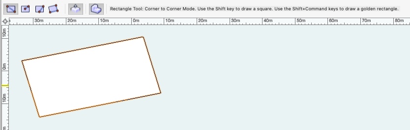
Thanks, Roy, but I don't understand. I don't know what a reactor is, and when I use that PL2REC command on a rectangular polyline (drawn with the RECTANG command), I don't see any change. The entity's properties don't change, and dragging a corner of the supposedly converted polyline still has the usual effect (see image). I assumed that "a rectangle behavior while stretching" meant it wouldn't do that any more and would instead stretch like a viewport. Is there something I need to turn on to make the reactor do whatever it's supposed to do?
When I use the TREC command, it tells me:
Unable to recognize command "RECTANGLE"0 -
Vectorworks' true rectangles can be manipulated just like BC viewports. When I worked in VW I used that all the time.
Talking about comfort,
it is not only about this :Creation
but also about :
Manipulation
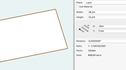
Do you see that Dummy Gizmo in Properties,
to select/define from which Origin, numeric changes will act from.Graphical Editing by 8 Grab points along Edge and Vertices,
to pull parallel or diagonally, +SHIFT to keep the aspect ratio,
however, it will stay a Rectangle.
Only when you use the Reshape Tool,
to add/delete Vertices, change Vertices to Bezier and such things,
a Rectangle will be exploded to a Polyline.0 -
Have to sympathize & agree 100% w/ Anthony:
WHY doesn’t a Rectangle maintain its “rectangleness”. If I wanted a parallelogram I should be able to Shift or Ctrl to release the “rectangle” characteristics of 90 degree corners & stretch to my hearts content.
Otherwise, it should remain a rectangle no matter which corner is stretched. Seems so logical as well as simple, how come no BCAD programmers or BCAD focus groups have come up w/ this “new” idea?
As has been stated, we can create rectangular Viewports w/ MVIEW, which maintain their rectangular shape even when stretched, which is so logical (most VPs need 90 degree corners) & convenient, (thank you code dude or dudette who was so forward thinking as to make that possible).
Whomever puts this kind of stuff on the “wish list”, please add this one. You will never know how many times a day you have saved millions of CAD hands the grief & extra time it takes to “fix” their rectangles after stretching corners to fit the geometric situation; I can’t count the number of times a day or even w/in the same dwg I do this. It has become such a habit I don’t even think about it, but bitch & moan the entire time it takes to "fix it". I keep asking myself "why doesn't someone fix this stupid command?"
But when the sweet & lovely person that DOES finally make RECANGLE work as it should, life will truly be good & there will be peace on earth.
Until we come up w/ another beef to discuss…..
Mike0 -
Maybe we just need the 3D Box Tool,
to have a Z=0 option.
(But still be able to manipulate its non existing "Side Faces" by PushPull Tool)So it would also already have a Fill
") 0
0 -
@Anthony Apostolaros said:
Thanks, Roy, but I don't understand.The fact that the Rectangle command is not recognized in your (German?) BC version is strange. The command is called with the underscore prefix in the Lisp code and therefore should work irrespective of the language version.
You can try changing the command name to the German equivalent.
Note that the reactor kicks in after a command has finished. So you will not see an effect while grip-editing a point. But when you have clicked the new point the polyline will reshape itself into a rectangle. The code works fine here (V18, English).
0 -
@Roy Klein Gebbinck said:
Note that the reactor kicks in after a command has finished. So you will not see an effect while grip-editing a point. But when you have clicked the new point the polyline will reshape itself into a rectangle. ....Ah, that's it -- I just didn't give it a chance. Thanks again.
I have English version 17, but my Help files say there's no RECTANGLE command, only RECTANG. The English online command reference says the same. Removing the "le" from the two (vl-cmdf) functions made the TREC command work.
0 -
Alan, Michael, and Mike:
Gilles' true rectangles stretch like rectangles even after they've been rotated!!0 -
Anthony,
Thanks for the heads up.
Tried registering on The Swamp, but bugged out when asked these 2 stupid questions:
1. Last name of the CEO of Autodesk? (HINT: Begins with `A'):
2. Name of the company that owns Bricsys? (HINT: One word answer):
Didn’t feel like answering stupid questions that have nothing to do w/ the lisp routine or problem @ hand.
And don’t feel like enabling someone just to satisfy his/her egomaniac tendencies.
Sorry, been a busy & insane wk, just can’t take any more BS for needless reasons.
Mike0 -
Mike, I think those are just robocheck questions. They probably figured .dwg users would already know the answers, but anyone can google them (Anagnost and Hexagon). The Swamp is a great forum, very Briscad-friendly, and those True Rectangle commands are well worth the hassle of signing in.
But I agree about security questions in general, which are often infuriating and discriminate against the elderly, asking things like the name of your first grade teacher, your first pet, your favorite rock band, or your favorite TV show (especially hard on those of us who've never owned a TV or listened to rock music).
0 -
For those who want rectangles to behave differently than AutoCAD, be aware that this introduces problems. A zillion people have been trained on AutoCAD and a half a zillion programs have been written to use the AutoCAD type of interactions and entities. Breaking those expectations will break confidence in BricsCAD.
It is OK, and even expected to add new features to BricsCAD. For instance adding a new command "ER" Edit Rectangle is OK, as long as it works with existing polylines that happen to be shaped as a rectangle. So, the idea of a program checking that there are 4 points, and that each corner is 90 Deg (or perhaps that each pair of lines are perpendicular) before allowing the command to work, is a great idea that maintains all the AutoCAD compatibility and interface standards.
-Joe
0 -
You can have recognisable "rectangs" its a block 1x1 called "RECTANG" just change X Y scale

Can have 1 with rectang based around centre point, 1/2 scale.
0 -
want rectangles to behave differently than AutoCAD, be aware that this introduces problems.
I agree with you, or think that is likely.
I think it would need to work by the modification tools, not the object itself.
Or kind of a BIM overhead, that Autocad can't see and only gets a cheap Polyline.0


