Ventilated facade for production

- What are the options for creating ventilated facades with all their elements? It should consist of the panels, the sub-construction behind them (not between like the curtain walls), the brackets attached directly to the walls and insulation (those are the main "layers" of ventilated facades). As these facade elements are defined by the manufacturer, they are usually found as library components. Is there a possibility to place those components to, lets say, defined grids (or something similar to curtain wall for eg, and not to place them individually?
- Also, the facade panels are separated from the carrying wall by air, which leads to the question of connection with the openings.
Thanks!
Comments
-
Hi Jelena,
Do you have a specific example of what you are trying to achieve?
A few options you might want to look at, are:- 3DARRAY lets you create a 3D array of entities/components : https://help.bricsys.com/document/?id=165079042589
- Propagate pattern is a powerful tool that lets you propagate components based on a pattern like a grid: https://help.bricsys.com/document?id=165079160119
- Our Grasshopper integration might also be helpful: https://boa.bricsys.com/applications/a/?rhino/grasshopper-connection-for-bricscad-bim-a1353-al2360
- You might also want to have a look at our 3D constraints engine: https://help.bricsys.com/document/?id=165079155532 and Youtube video
I hope this helps; let me know if you need more info.
Best regards,
Ruben
-1 - 3DARRAY lets you create a 3D array of entities/components : https://help.bricsys.com/document/?id=165079042589
-
Hi
it's not our main task in application SYSCAD, but it's possible.
You could find more info's here: https://www.syscad.org
Regards
Wolfgang Gruber
SYSCAD TEAM GmbH
0 -
Thanks, these tools seem helpful!RubenDBricsys said:Hi Jelena,
Do you have a specific example of what you are trying to achieve?
A few options you might want to look at, are:- 3DARRAY lets you create a 3D array of entities/components : https://help.bricsys.com/document/?id=165079042589
- Propagate pattern is a powerful tool that lets you propagate components based on a pattern like a grid: https://help.bricsys.com/document?id=165079160119
- Our Grasshopper integration might also be helpful: https://boa.bricsys.com/applications/a/?rhino/grasshopper-connection-for-bricscad-bim-a1353-al2360
- You might also want to have a look at our 3D constraints engine: https://help.bricsys.com/document/?id=165079155532 and Youtube video
I hope this helps; let me know if you need more info.
Best regards,
Ruben
More about the connection with the windows:
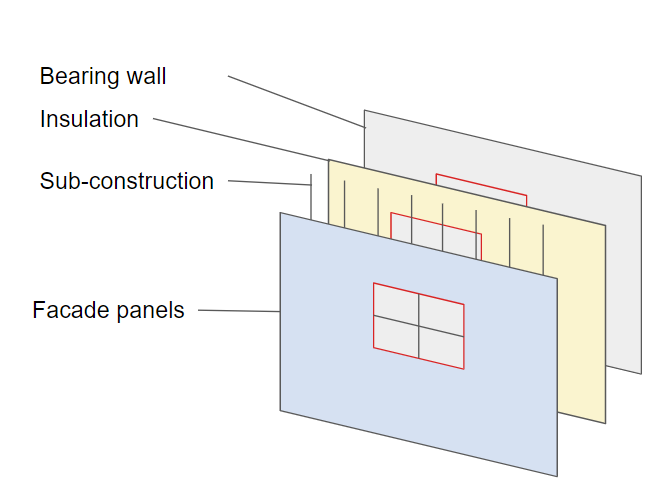
Ventilated facades contain several layers (mainly bearing wall, thermal insulation, sub-construction, air, finishing panels). Each of them needs to be in BOM, for the overall project prices and also for the material purchase / manufacturing (which is why I'd need as detailed model as possible, and not just thick wall for eg.).
I am attaching the images of the layers and their relation to the openings, as some examples. All of the layers should be "interrupted" by the opening. Also, the sub-construction elements as well as the facade panels, have particular types that go around those openings (eg. jambs, sills for windows). And I'd like to know if it is possible to set this principle up without too much manual work. For large facades for example it would be super time consuming to set them individually.
Note: Maybe I am asking something obvious, I have no experience with BricsCAD. I am considering to use it though")
0 - 3DARRAY lets you create a 3D array of entities/components : https://help.bricsys.com/document/?id=165079042589
-
Hmmh .....
The first one is easy.
For a ventilated Wall you will create a Composition (a Wall Style)
You will define each Wall Ply and dimension, including Air Gap.
After that, I hope you do not need to detail the sub construction in 3D !?
That would not be fun ....
I hope you could show/define this by detail plans.
For the Bim Model itself I would see it as a standard Ply setting,
maybe with a reasonably faked looking Hatch or so.
This way, the whole Wall, including all Plies will be cut automatically e.g.
by an inserted Window
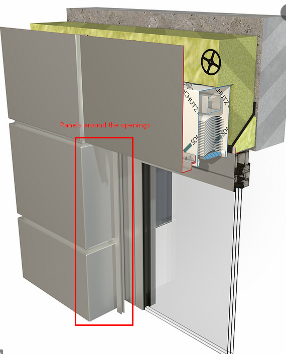
Third, Panels around the openings ....
It depends what it will be in reality.
1. a separate Frame/Cover
2. part of a Window,
3. the outer Ply of the Wall extending inwards into the opening.
....
1.
Could be a simple series of Blocks according to opening dimensions
or even a parametric Block
2.
Could be a custom Window, Door, Opening...
You can create any complex Subtraction Volume for the resulting Opening
and complex Framing/Covering inside your Windows.
Either create separate Component Duplicates for each situation or have fun
with abstract Constraint to build a total parametrical and complex Window.
3.
This is usually the typical Bricscad workflow when detailing the BIM Model
further to meet a certain BIM LOD : Propagate
You will model the Wall Ply details around one Opening, run Propagate,
which should find all similar situation and model the other openings for you.
0 -
Thank you, this info means a lot!Michael Mayer said:Hmmh .....
The first one is easy.
For a ventilated Wall you will create a Composition (a Wall Style)
You will define each Wall Ply and dimension, including Air Gap.
After that, I hope you do not need to detail the sub construction in 3D !?
That would not be fun ....
I hope you could show/define this by detail plans.
For the Bim Model itself I would see it as a standard Ply setting,
maybe with a reasonably faked looking Hatch or so.
This way, the whole Wall, including all Plies will be cut automatically e.g.
by an inserted Window
Third, Panels around the openings ....
It depends what it will be in reality.
1. a separate Frame/Cover
2. part of a Window,
3. the outer Ply of the Wall extending inwards into the opening.
....
1.
Could be a simple series of Blocks according to opening dimensions
or even a parametric Block
2.
Could be a custom Window, Door, Opening...
You can create any complex Subtraction Volume for the resulting Opening
and complex Framing/Covering inside your Windows.
Either create separate Component Duplicates for each situation or have fun
with abstract Constraint to build a total parametrical and complex Window.
3.
This is usually the typical Bricscad workflow when detailing the BIM Model
further to meet a certain BIM LOD : Propagate
You will model the Wall Ply details around one Opening, run Propagate,
which should find all similar situation and model the other openings for you.
If I understood correctly, if a wall is not a single entity (wall ply layers), but there are additional elements of facade sub-construction, there is currently no defined way to connect these so they all recognize openings and define sides around them (jambs).
Unfortunately, I do need the sub-construction in as much detail as possible, because I will use it for BOM (ordering elements, checking sizes, positions, manufacturing, etc). And it would help to have them in 3D.
There are other software (eg. SolidWorks and HiCAD) that do this, but I wonder if BricsCAD had this option too (without the painful manual process of course), since it states on the official website that various industries (eg. Manufacturing, Product design, as well as Architects) would benefit from the software. Plus, the project design workflow seems user-friendly. Also, there is a video showing some facade concstruction elements (panels, sub-construction, screws) in 3D (attached screenshot), which gave me hope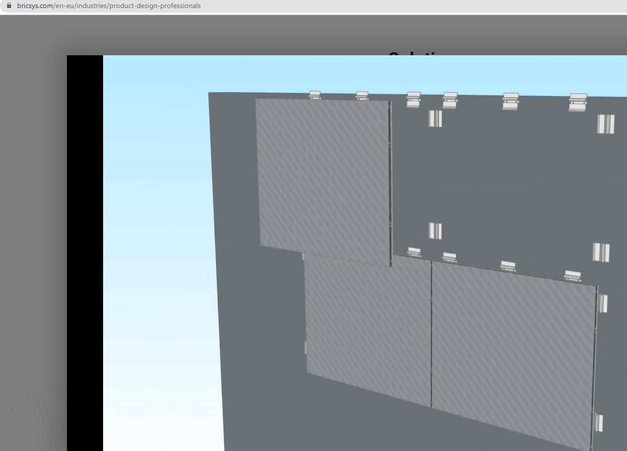
0 -
Thanks for the screenshot.
OK, in this case I do not see your Facade layer as part of the Wall Plies.
I do not have the experience in Bricscad of what is the best way to do.
I do similar things but in a more reduced way in Vectorworks.
Because of the strength and weaknesses of each CAD, it this case
I create a single Extrude of all panels of a whole facade.
As the 2D tools inside the Extrude Edit Mode are more comfortable.
But beside arraying the Rectangles, there is still much manual adaption
around openings and special situations.
And if your Building is not a simple Cube, this means easily far more
Extrudes than just 4 for all sides.
And if your clients wants to test Variants of different grid sizes, you do it
all over again.
I fake the Panels by extruding over the Air Gap until the Wall. This way
my simplified version does not need extra covers around Openings.
Just that I need to manually cut/adapt Rectangles around openings before.
Potentially needed coverings inside the Wall opening are part of
my Windows.
So it looks for me but not applicable to your case.
If I would need it more complex/realistic, I would also switch to using
arrayed Panel Blocks.
In your case ...
I assume each single Panel is a Block as well as each Fitting, nested/combined
in a parent modul Block.
A BIM Grid and AI Propagate Command would array all Moduls over the Wall.
Modul copies intruding into Openings have to be deactivated manually.
And possible also manually filled with special Moduls around the openings.
Maybe it is wise to separate arrays of Panels vs arrays of fittings.
I am not sure if Propagate is able to also distribute your side panels around
each Opening automatically, at least not in one go.
And it all depends on how complex your openings are ....
If you use only a single Opening Size and even adapted to the Panel Grid,
this could be really easy.
(That is what your first detail screenshot promises)
While when Openings cut Panels in any dimensions and locations into
multiple sizes and even L-shapes, you will easily get nearly more special
Panels than regular ones and endless manual adaption work.0 -
Thank you MIchael for such detailed answer!
In conclusion, BricsCAD is yet to be developed for these needs. That is what I wanted to know 0

