FLOW CONNECTIONS/FLOW TERMINALS

I am having trouble building a component with flow connection points for BIM, in this case it is a 2.5 inch open and close valve. This valve can accept a 2.5 inch pipe from either end. I have followed the help document link below. I have BIM classified the valve as a "flow terminal". I then created a 1/2 inch circle placed in the middle of the valve and BIM classified it as "Flow Connection". Because this seemed to work the best as a work around.
The problem that I am encountering is:
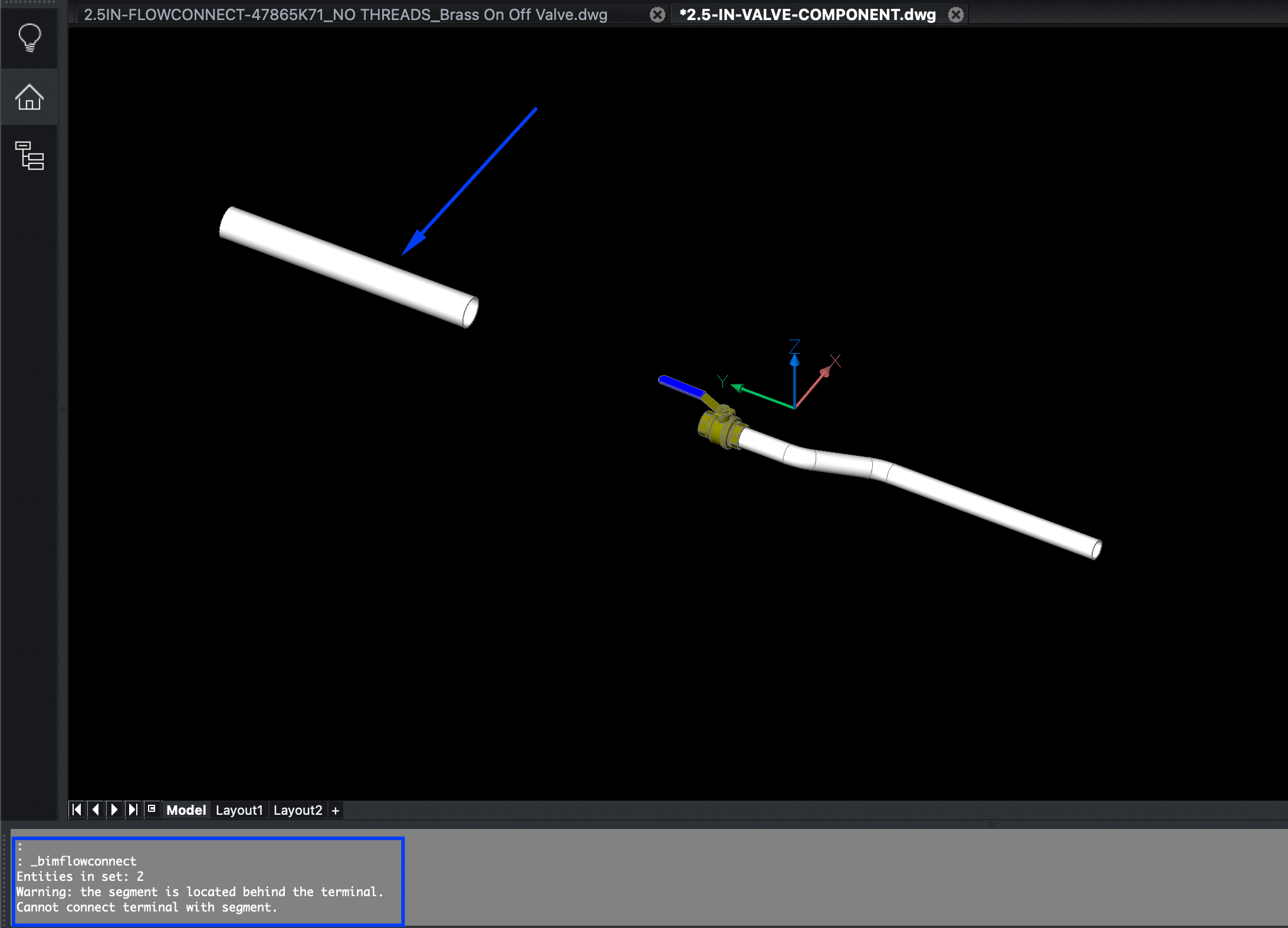
1) I tried to create two flow connection points and placed them at the ends of the valve. One in the back and one for the front. I can get a round pipe profile to connect one one side, however, when I create the same profile behind the valve I get an error "Warning the segment is located behind the terminal. Cannot connect the terminal with the segment." I have attached an picture with the error "Valve-Error-1". The only way that I can connect the segments together is by selecting the pipe segments and "connect flow segments".
a) are you able to add two flow connections points to this valve component or any other components I want to build? And can I have segments connect to each respective flow connection point that I choose? I just cannot figure out a way to do this?
b) If you are only able to work with one flow connection point per component are you able to have them connect one either side of this valve (or either side of the flow connection point), instead of me connecting the flow segments?
I have attached the drawings that I am working with:
2.5in-flowconnect-47865.... This drawing has the valve and the flow connection BIM classified as a flow terminal and flow connection point respectively.
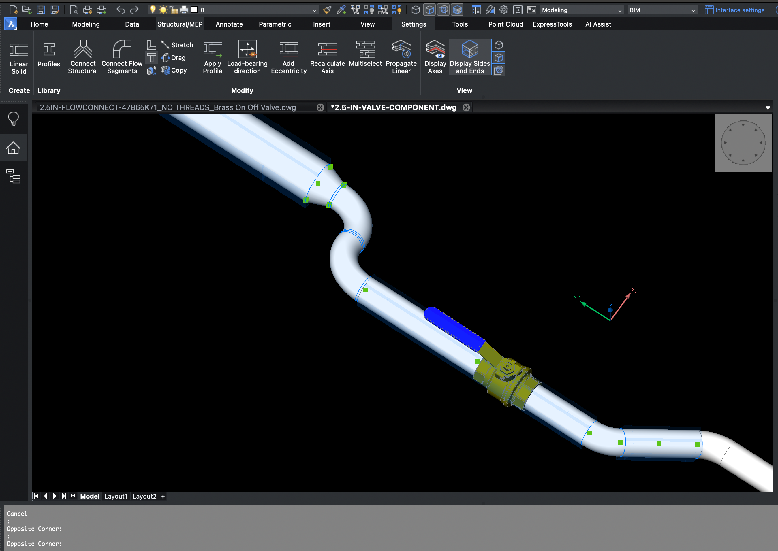
2.5in-valve-component this drawing is the actual component.
I am building a compressed air piping layout and I need all the valves and other components that I add to move when I adjust the piping segments accordingly.
Appreciate any Help,
Regards,
Beto
Comments
-
Try these. I marked the circles as "Flow Connection Point"
As per this guide.
https://help.bricsys.com/document/_guides--BIM_modeling_techniques--GD_mepflowconnectionpoints/V22/EN_US?id=165079162663
I can connect on either side ok.0 -
I do not really get this ....Linnemann said:Try these. I marked the circles as "Flow Connection Point"
As per this guide.
https://help.bricsys.com/document/_guides--BIM_modeling_techniques--GD_mepflowconnectionpoints/V22/EN_US?id=165079162663
I can connect on either side ok.
- you can add two "connection points" in "Flow Connection Point" config ?
- a "Flow Terminal" can only have a single connection point and so only a single connection ?0 -
Michael,
Trying to understand your comments:
-you can add two "connection points" in "Flow Connection Point" config ? FROM YOUR KNOWLEDGE AND UNDERSTANDING, ARE YOU SAYING THAT TOU CAN ONLY HAVE ONE CONNECTION POINT.
-a "Flow Terminal" can only have a single connection point and so only a single connection ? ARE YOU UNSURE OF THIS AS WELL. ARE TOU SAYING THAT YOU CAN MULTIPLE OF THESE.
Linneman, I will test and revert.
Thx0 -
I have no knowledge at all.
I looked at MEP at earlier (linear Solids) versions and could not get it to work for me.
But as it is a cool feature to be able spread some basic MEP in a building,
I tried it again in V22 (?) and it worked for me.
But so far I only played with Pipes, T-joins and reducers - no connection points.
So at first I thought maybe your Valve can only have one connection point
and you would have to connect the pipes from both sides .... until I read
"Warning the segment is located behind the terminal. Cannot connect the terminal with the segment."
Looks like I should also read the help guide first and get used to the terms,
or even watch the presentation videos about MEP again.0 -
According to this
https://help.bricsys.com/document/_dialogboxes--DB_classifyasbimelement/V23/EN_US?id=165079122924
This is what a valve should be.
Flow Controller
The occurrence of elements of a distribution system that are used to regulate flow through a distribution system.
Example: damper, valve, switch, relay
Also
Flow Connection Point
The connection point is used to describe the geometric constraints that facilitate the physical connection of 2 objects at a point.
I understand this as, if you want to connect a valve and a pipe in both ends that would be 3 objects and not 2.
0 -
I'm using the MEP tutorial file and there is a strange thing here.
If you only select two components and run BIMFLOWCONNECT I get the error "Cannot determine connection type."
But if I select more than 3-4 Bricscad can route them fine?? 0
0 -
I tried the files that you sent and they did work. But I just cannot repeat it. Perhaps my order of operations is wrong or I am doing something incorrect somewhere.Linnemann said:Try these. I marked the circles as "Flow Connection Point"
As per this guide.
https://help.bricsys.com/document/_guides--BIM_modeling_techniques--GD_mepflowconnectionpoints/V22/EN_US?id=165079162663
I can connect on either side ok.
In Summary I tried this from what you have mentioned. I have classified the valve as a "Flow Controller" and "Flow Moving Device" and I still get the same type of errors.
What is your order of operations? This is what I did.
Valve= Create the valve->BIMClassify-> Flow Controller I also tried Flow Moving Device
Circles= Create circle(s)->Place the circle where I want the connection point(s)->BIMClassify->Flow Connection Point.
I want to point out that when I BIM classify the circles as connection points I only classify the circle and not the circle and valve together.
I don't know how to upload a video like you did above. I am providing a link to a video that you can download.
https://wetransfer.com/downloads/850260e88a11d929b03ae7993115465e20230317062803/80e0aee93f55ecaba7af643a20e2323a20230317062846/12ed38?trk=TRN_TDL_01&utm_campaign=TRN_TDL_01&utm_medium=email&utm_source=sendgrid0 -
Can you explain what the issue is? Is it that it wont connect from the other side?
You have to make sure that the two parts you want to connect are in the same plane.0 -
Yes that is the issue it will not connect to either side. When I try to use two connection points I get errors. When I only use 1 connection point they will connect on either side of the connection point, but i dont accomplish connecting at either end.Linnemann said:Can you explain what the issue is? Is it that it wont connect from the other side?
You have to make sure that the two parts you want to connect are in the same plane.
Your drawing that you uploaded worked. What was the exact order of operations that you did?
I am starting to think that its a bug. I am running on MacOS.0 -
Hi
Ive made a movie with all my steps.
See at the end that if the parts are not alligned the parts will not connect.
Do now know why that is.
FYI, I'm using ScreenToGif to make my videos.0 -
Linnemann,Linnemann said:Hi
Ive made a movie with all my steps.
See at the end that if the parts are not alligned the parts will not connect.
Do now know why that is.
FYI, I'm using ScreenToGif to make my videos.
First of all thanks for your help and time. In Summary, I think this is a bug. I have uploaded two videos.
I classified everything the same as you did and I can get it to connect. But as soon as you mentioned if it is not aligned it will not connect. But I am afraid I am worse off, you were able to make some connections, while I tried to repeat the same thing, and I cannot connect or I get a very weird option to connect.
Are you working on Windows or Mac?
Thx0 -
I'm on Windows.
I would make a ticket with Bricsys support as I do think there are some issues with the MEP connection stuff at present.0
