How to add a reference system grid to a viewport?

Is it possible to add a reference system grid to my viewport, like autocad map: https://help.autodesk.com/view/MAP/2024/ENU/?guid=GUID-30F7E71E-5E9D-467C-8630-3795A23193EA?
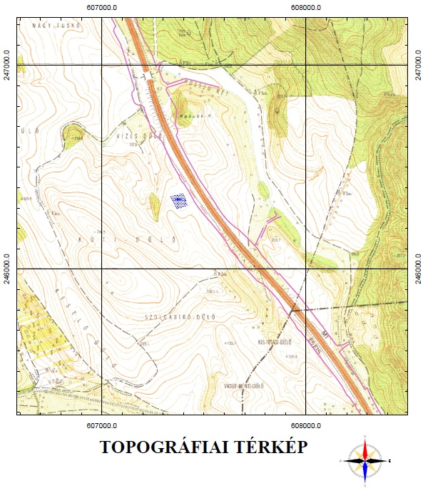
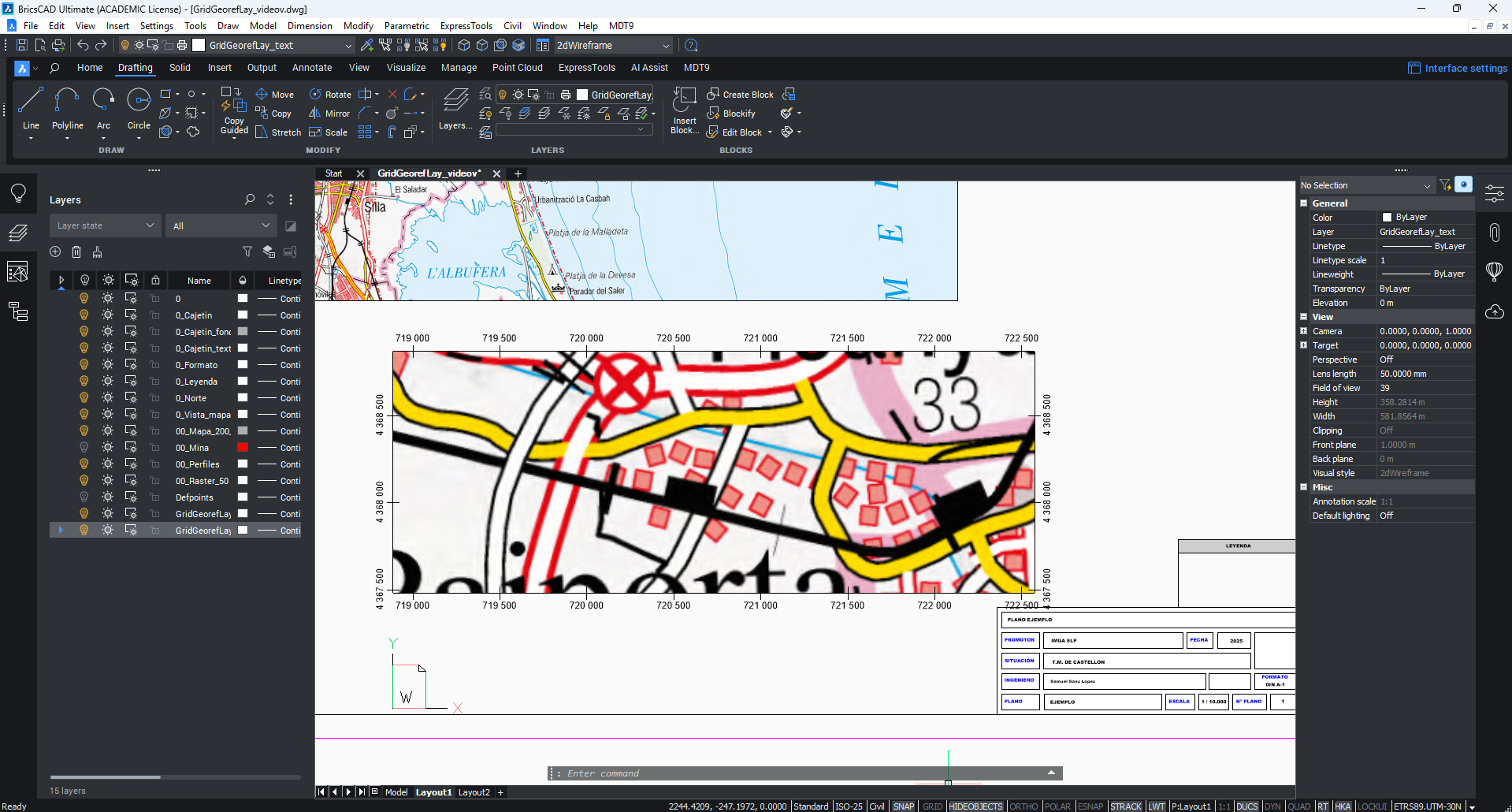
I attached a picture of what I want to do.
Thanks,
Comments
-
There is no such a feature in BricsCAD. You can send a feature request about it, so it could be considered by developers: https://boa.bricsys.com/protected/support/NewSupportRequest.do0
-
Thanks!
0 -
@Tamás
Hi.
first - same with me,hope bricscad will make this feature.
for the mean time here are 2 lisp's I found & use:
1. for model space "DrawGrid.LSP"
2. for paper space "KoordinatenRand.lsp".0 -
I have something that draws grids on a viewport, the viewport can have a twist angle so grid reflects this.
PM me and can discuss.
2 -
I made some changes to KoordinatenRand.lsp and added some functions. I think this could be useful for anyone who wants to create a geo-referenced grid.
Download link:
I’m also sharing the file.
With this file, you can change the position of the text and lines, placing them inside or outside the view. The program is designed to work in layout mode. You can also choose between different line lengths.
Thanks you
1 -
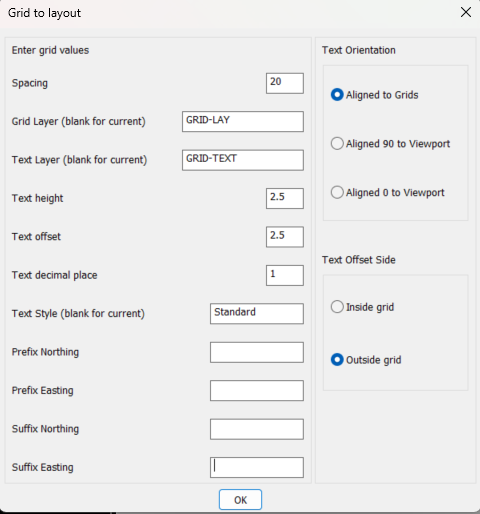
I have made some more modifications to the lisp, now it includes multiple functions:
Default vs. Manual Settings:
Choose to use preconfigured default settings or enter parameters manually.Automatic Layer Creation:
The script ensures that two layers, GridGeorefLay_marks (for the lines) and GridGeorefLay_text (for the coordinate labels), exist, creating them if necessary.Dynamic Number Formatting:
Numbers are formatted with spaces as thousands separators for better readability.Customizable Text and Line Placement:
Decide whether text labels are drawn inside or outside the viewport and whether grid lines are drawn inside, on, or outside the border.Step Size Calculation:
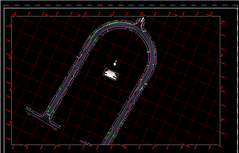
When using defaults (or by choosing the predefined option in manual mode), the script calculates an appropriate step size so that the grid marks appear at “round” numbers (e.g., 0, 50,000, 100,000, etc.) based on an allowed list of measures.Examples
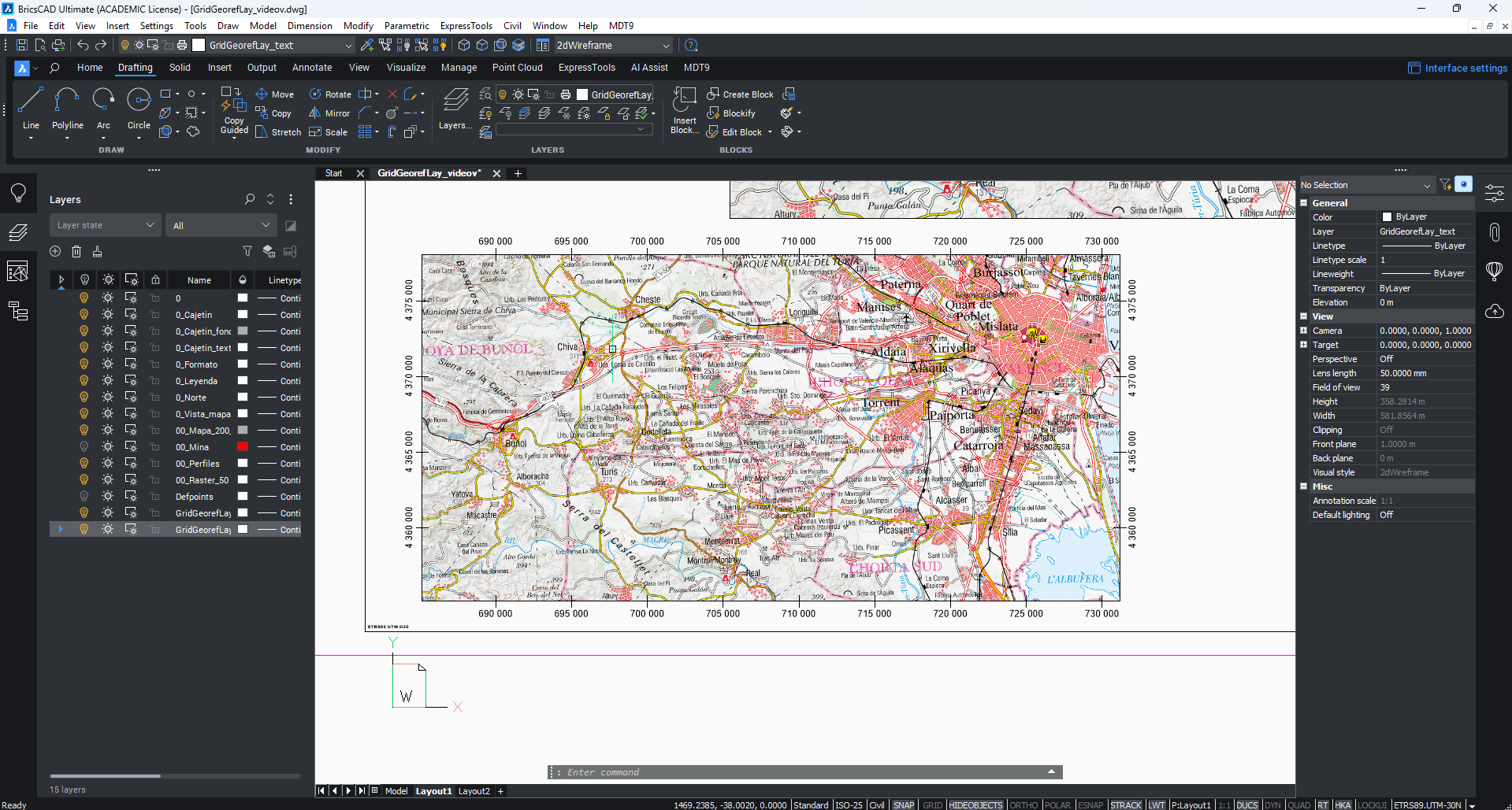
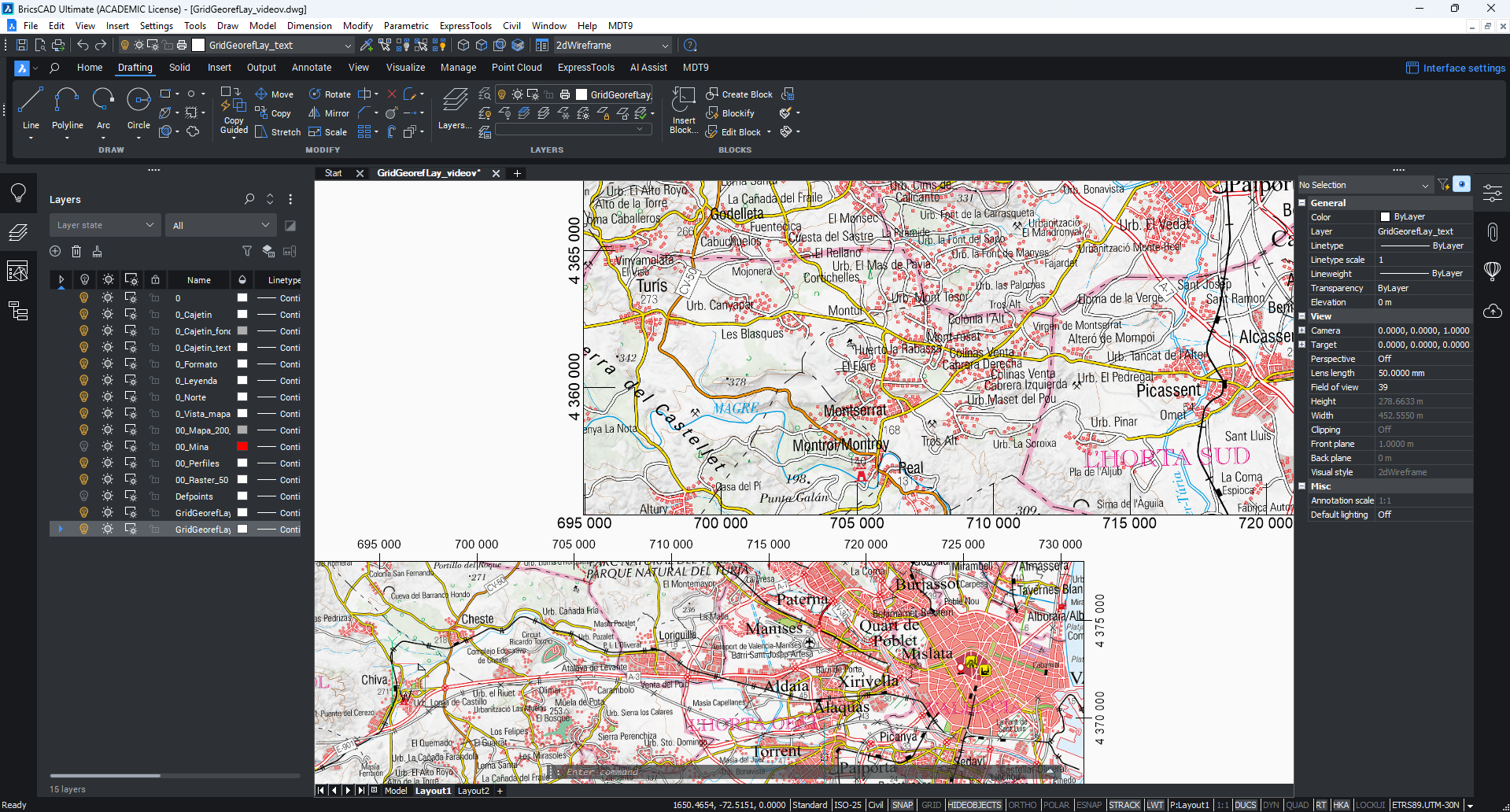
I also create a repository on GitHub, I will upload future modification there.
https://github.com/samuelsl27/GridGeorefLay.lsp.git
Any cuestión ask me
Thanks you
2 -
If you look at the image I posted the viewport has a twisted view so the grid labelling is still in correct orientation, I did not see any twisted views in your images, may be a feature to add.
0 -
Hi @ALANH i think that you forgot to upload the image or some error has happened. I think that I understand what do you want but I'm not sure. Do you mean that you north its tilted? Are you trying to plot this into road map?
First, to implement this feature I need to know how to do this in BricsCad, I don't know how to tilt the map in the viewport. If you can explain how to do it I try to implement.
Thanks you
0 -
Its the image in the 5th post, I was just suggesting you may want to add the ability to do grids where a different UCS has been used, my code auto detects, we did this for road designs where we tried to keep the road horizontal on a plan. Another example the rectangs are the layout views rotated to be horizontal in layouts.
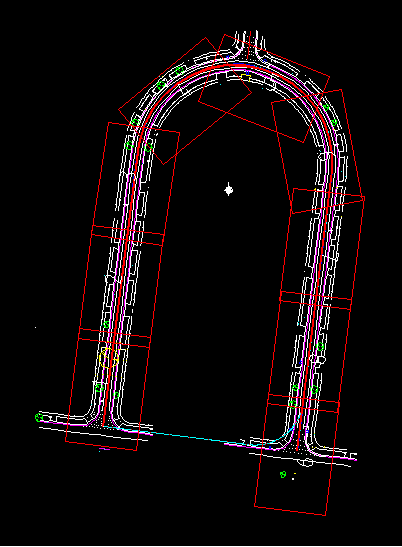
Just a PS the rectangs are at scale matching a title block and were created by walkiing along a pline. Then layouts are made by selecting the rectangs, have made 100 in one go.
0