Low resolution of revolve

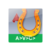
Why resolution of revolve with my model is so ugly please? Export to 3D printer is the same. Thanks
Comments
-
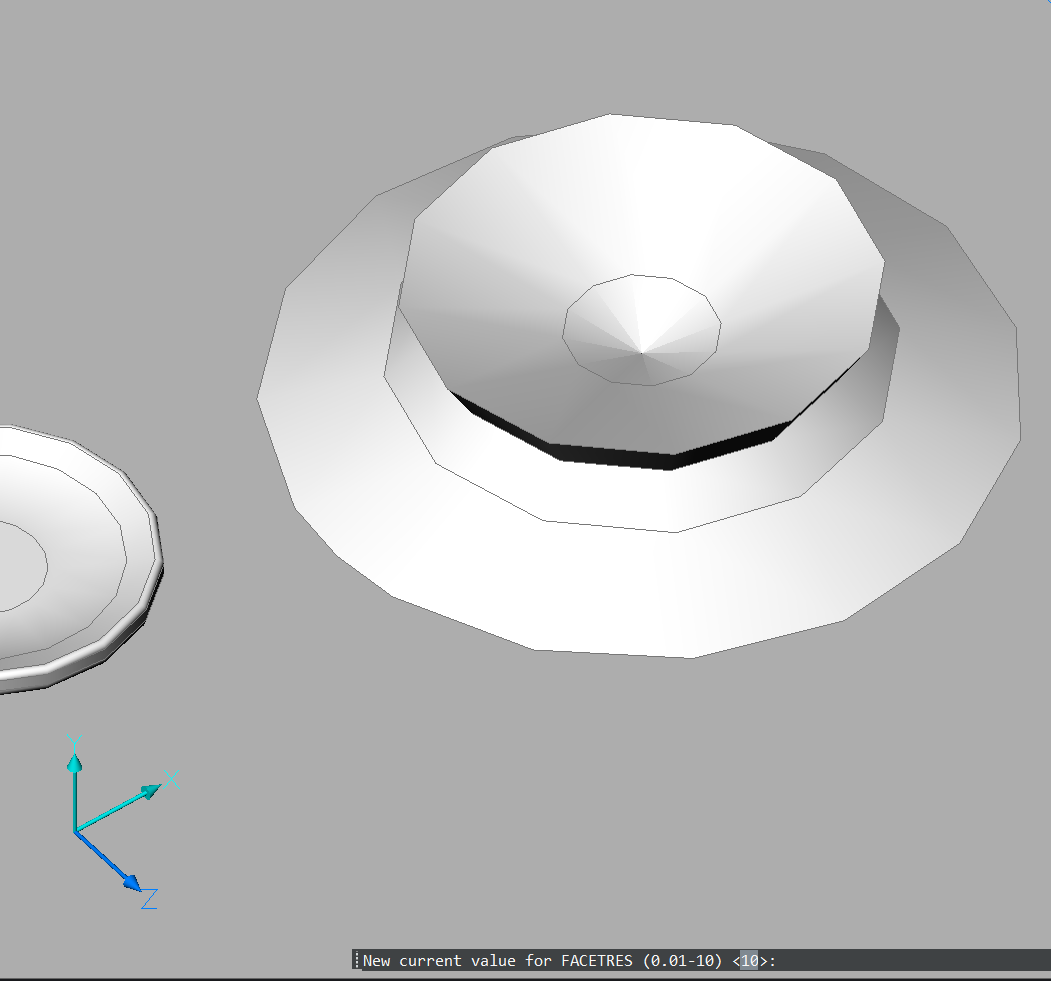
_facetres 10
0 -
I tried this, this is facetres 10 before revolve
 0
0 -
This is file …
0 -
Try the next settings in the Settings dialog: SpaUseFacetRes = 0, SpaSurfaceTol = -0.1, SpaNormalTol = 15 and SpaMaxNumGridLines = 3000 (last two are default values, check them just in a case they were changed). Run Regen after that to see difference.
0 -
Assuming you're using STLOUT to generate your 3d print file.
Then the value of FACETRES will change the resolution of the generated file.
Jason Bourhill
CAD Concepts Ltd
0 -
I also noticed very coarse display of round objects.
I thought it would be a lower graphic/GPU default setting since V26.
0 -
OK, it is "partly" FACETRES setting - which defaulted to 0.5 here !
So I set it to "2"
Now I see that my Cylinder sides look better.
But unfortunately the circular Top and Bottom Faces of the Cylinder are still a coarse 12 vertices Polygon.
What you will notice even more, as now there appears a nice Circle along the Top Polygon.
(Which I think is the of the Face of the Cylinder Wall sticking through)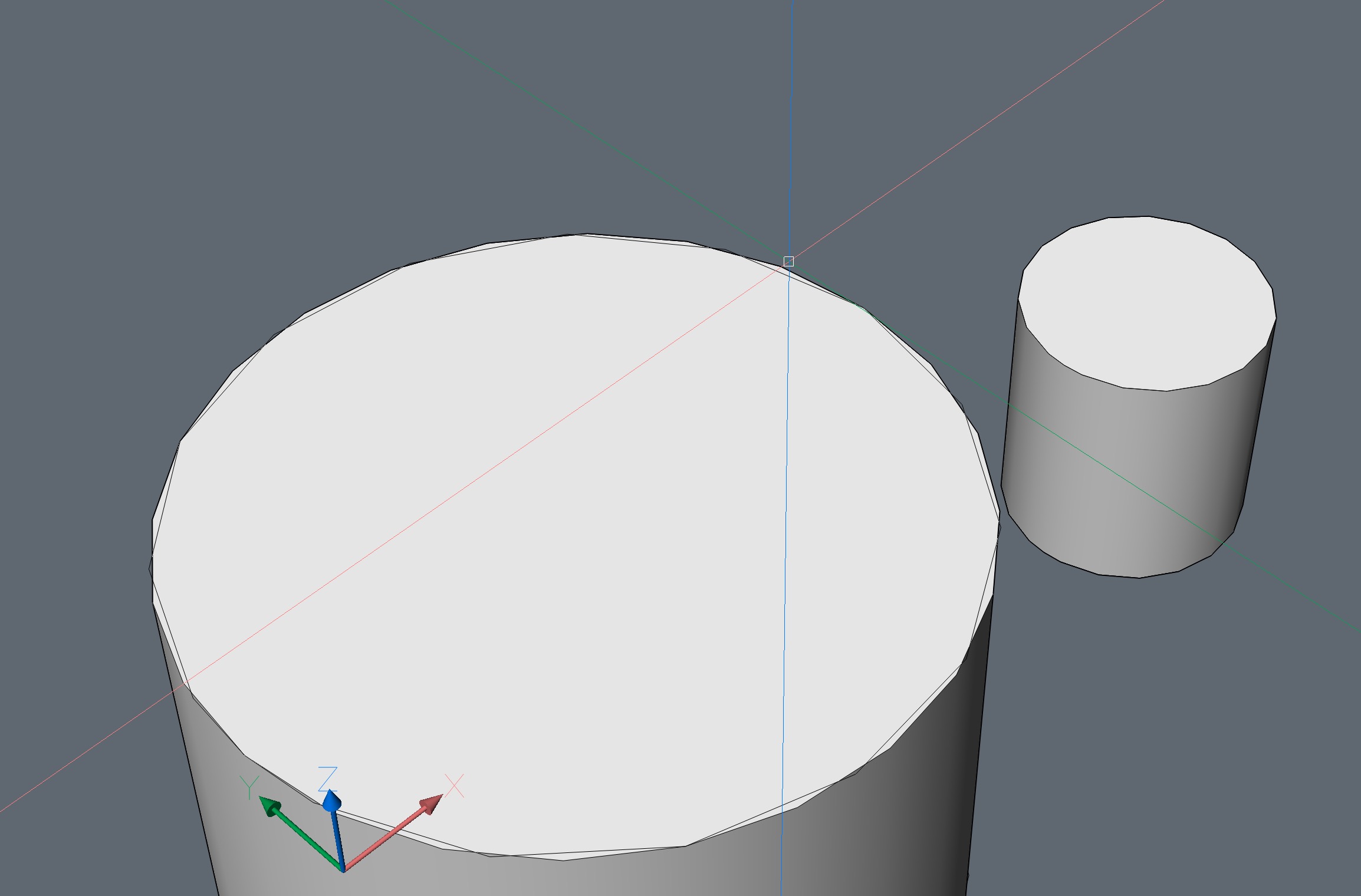
EDIT :
No Circle - also a Polygon - both do just not match, slightly rotated.0 -
I think it is a GPU Setting issue.
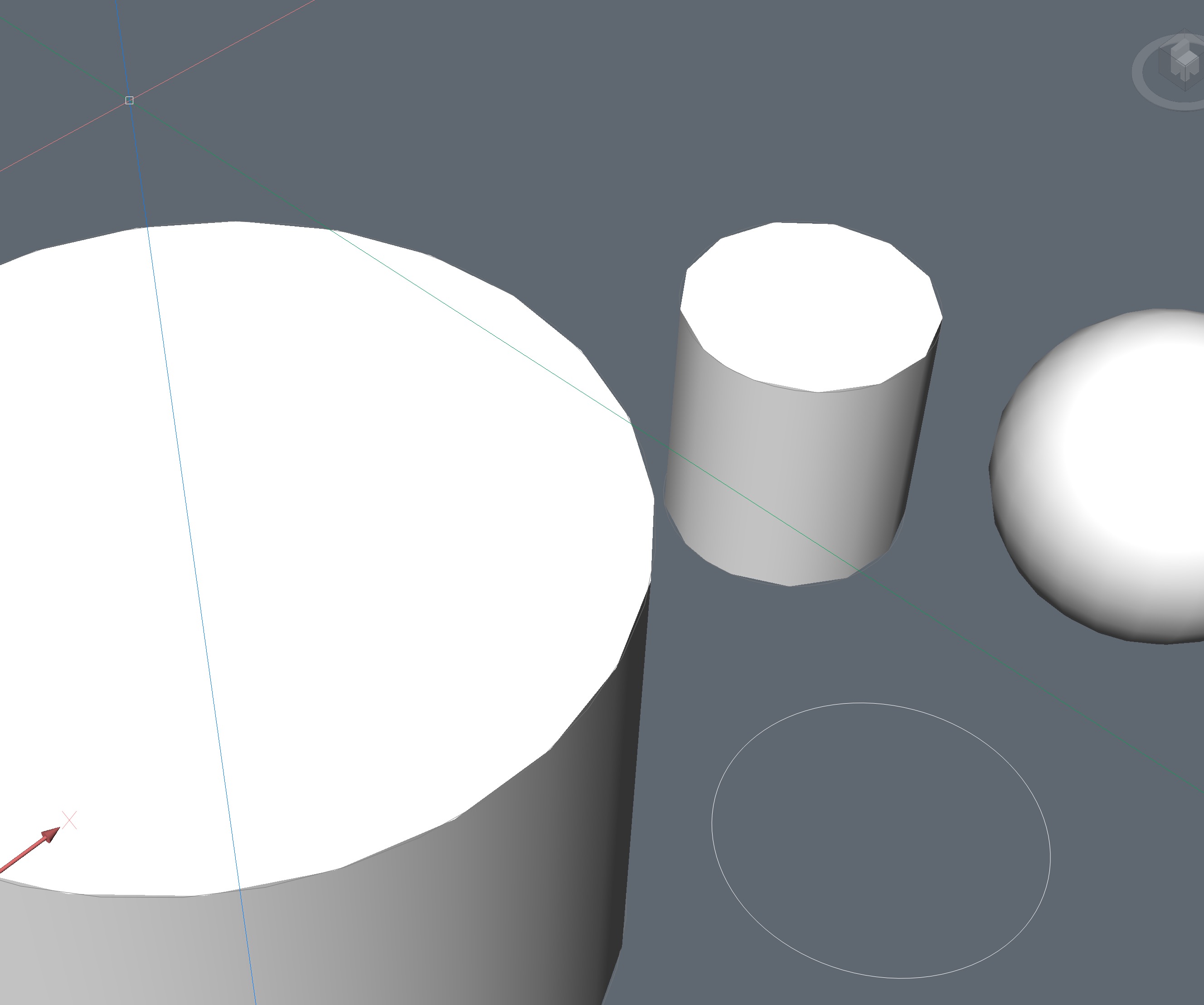
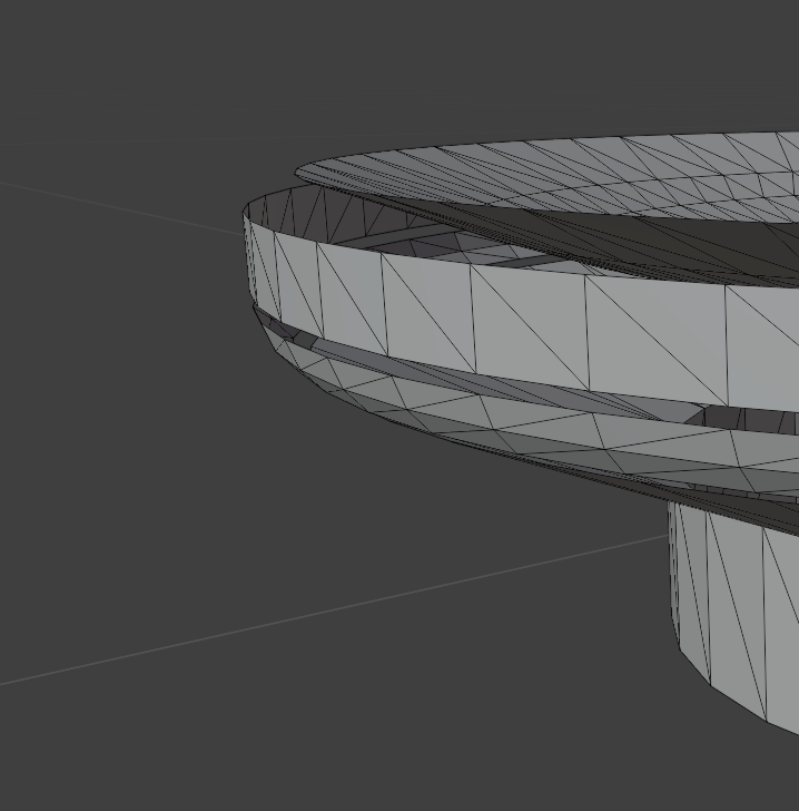
The 2D Wireframe Mode Display Mode is good, but everything 3D Shaded (RedSDK) looks crappy, even 3D Wireframe Mode
2D Wireframe OK :
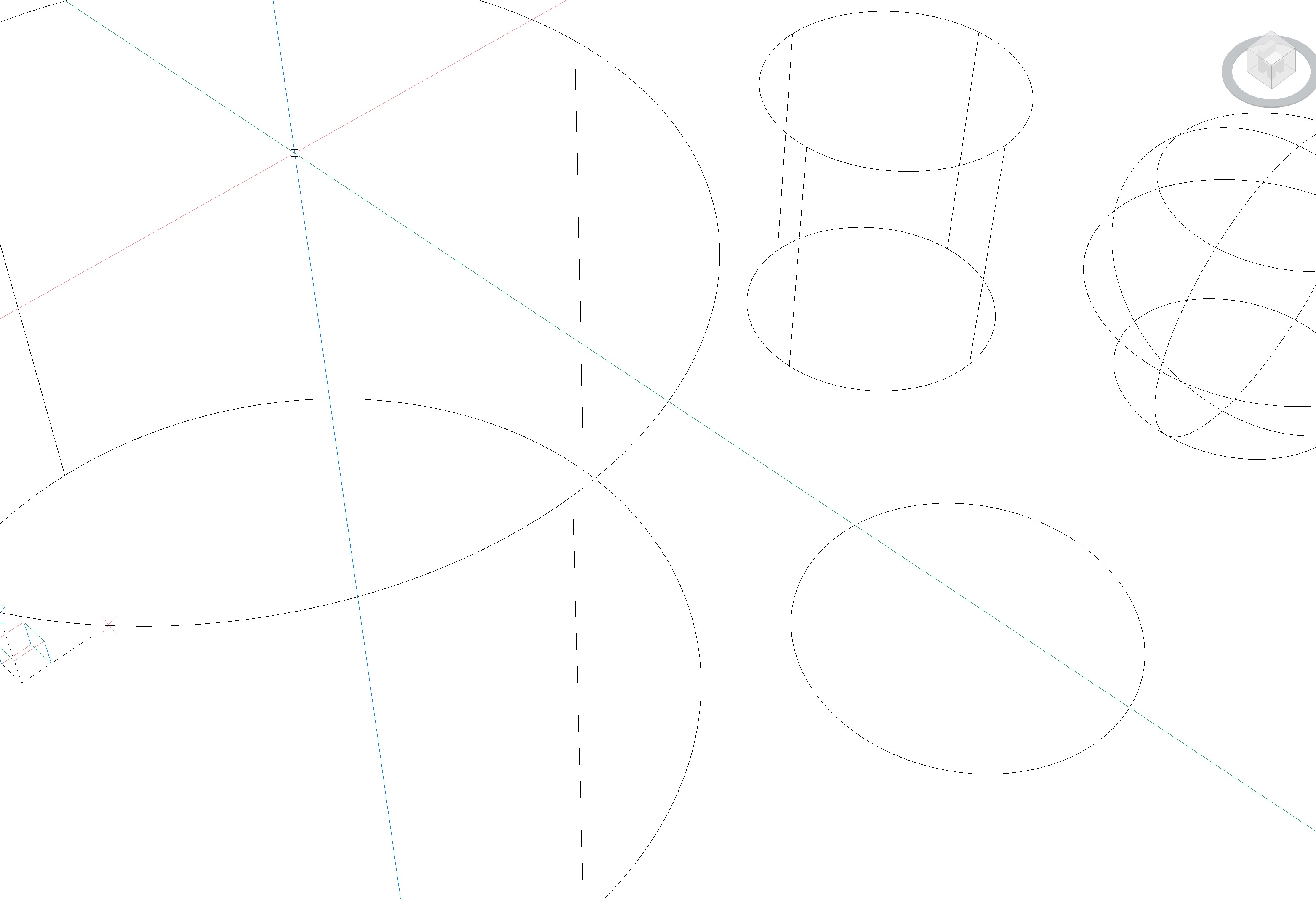
3D Wireframe bad :

3D Modelling bad :
 0
0 -
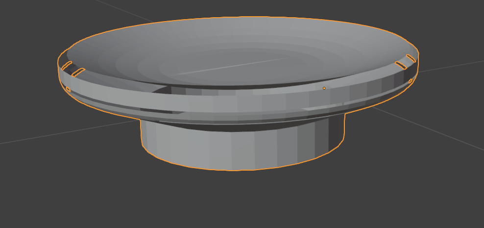
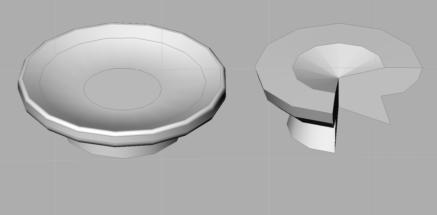
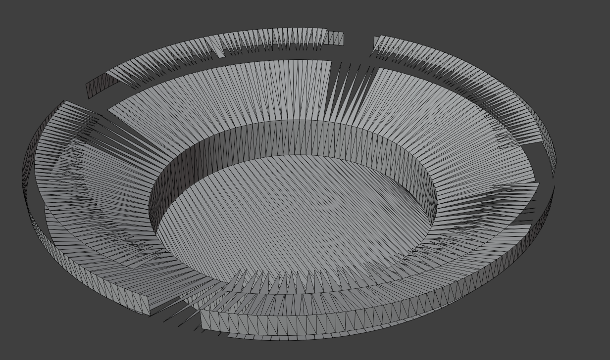
Exported Stl in Blender looks like this, it is completely wrong. I generally use Blender to make my 3D models for printing , now I try to switch to Bricscad, but I am surprised as I am not able to make easy things.
0 -
2D wireframe is the only style that is 'true' - all the others incl 3D wireframe are Rendered, produce the same approximate-geometry screen display. I'm not sure quite what 'true' (my word) and Rendered mean, but they're mighty different. AFAIK outputs, printing incl 3D printing will be unaffected by the screen Style.
0 -
Looks like FACETRES resolution helps.
Looks better with 8. Maybe it needs the maximum of 10. Still not round but less shabby :)
0 -
Hello, thanks for answer,
but I am still not able to export my easy model od soap holder to 3d Printer slicer.
Why it is so difficult to make this truly easy thing? In Blender it is done in 5 minutes without mistakes.
With facetres 8 is STL result absolutely bad. After one week trying...
I think such kind od easy model should work immediately. It is worth trying to continue? Thanks
 0
0 -
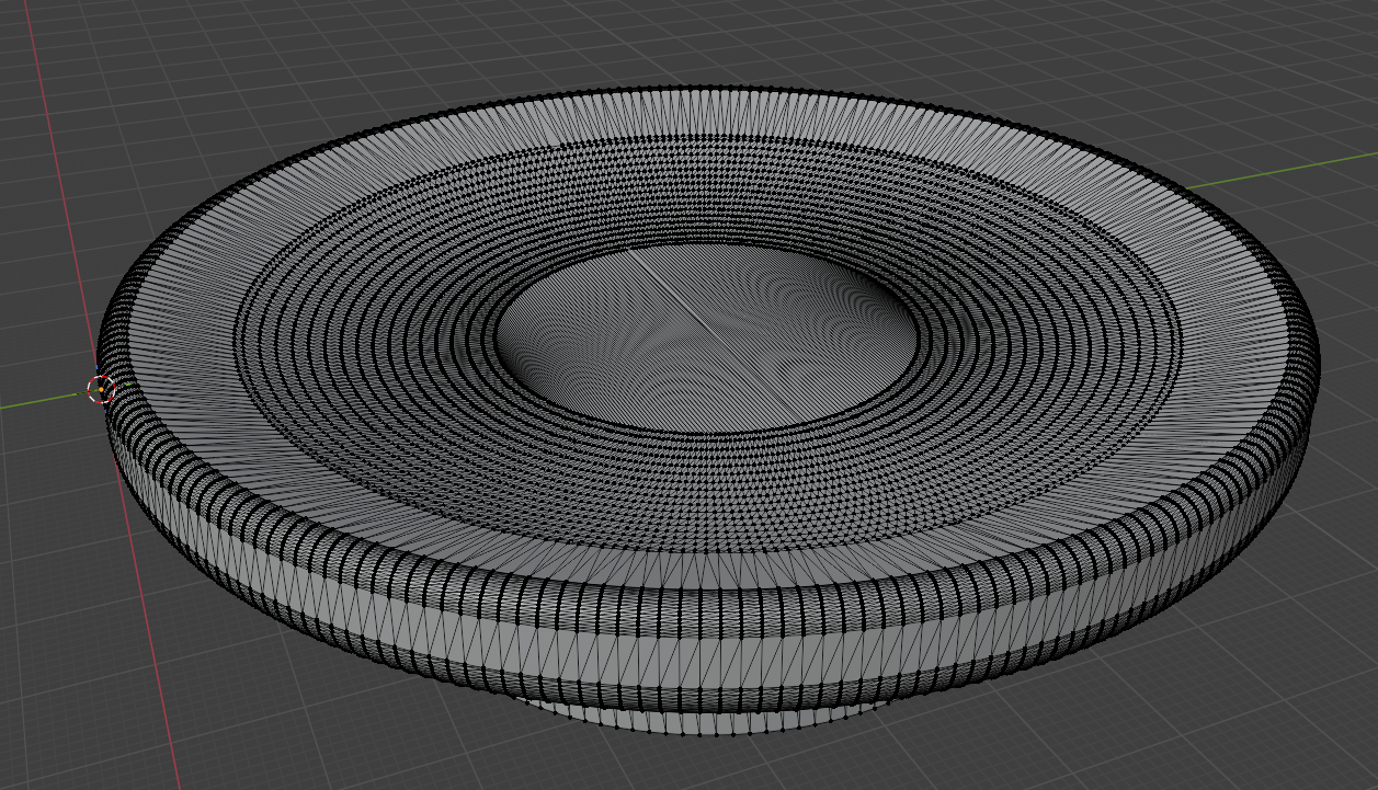
The issue looks to be that you have generated your model in metres. This is effecting the resolution of the generated STL file.
I scaled your model up by a 1000 and change the UNITS to mm. Following this STLOUT on high resolution gave a good result.
Jason Bourhill
CAD Concepts Ltd
0 -
My job is 2D drawing pipe systems in houses, I use always meters in my files.
So I will try to use mm for smaller models 3D, and yes, in mm it looks good now.
But my dimensions was OK , 0,1 m = 100 mm , both are OK, and maybe should be OK in BC too…
So, my problem is maybe feature of program, not mistake, thanks for answer…
 0
0 -
With facetres 8 is STL result absolutely bad.
If I got that right, FACETRES Setting is only for 3D Drawing View Modes.
No clue if there are any further Settings that influence real Geometry or any Exporters.0 -
The problem is most like due to the number of places available after the decimal point. For objects smaller than 1.0 x 1.0 x 1.0 in size the number of significant figures available to describe the model are limited, which results in inaccuracies.
You can visualise this if you output the STL in ascii format. This is an example from the OP drawing file "Mydlo.dwg". Due to its small size it is only using 5 significant figures to describe each facet
facet normal -0.040225 0.000000 0.999191

 outer loop

  vertex 0.091547 0.059951 0.030195

  vertex 0.086694 0.058983 0.030000

  vertex 0.091547 0.058014 0.030195

 endloop

endfacet
This is an example from the "Mydlo_mm.dwg" where the model was scaled by a factor of 1000. In this case it is using 8 significant figures to describe each facet.
facet normal -0.040057 -0.000839 0.999197

 outer loop

  vertex 72.044952 49.960995 20.205334

  vertex 67.176743 49.756958 20.010000

  vertex 67.192749 48.992634 20.010000

 endloop

endfacet
With small objects increasing the FACETRES probably has the opposite effect, as this is dividing the object up in to more smaller facets, which can't be described adequately with the available significant figures.
The STL file format is unitless, but it would need to be declared at the point of printing, which assumingly would be either mm or inches. Potentially other applications are applying a scale factor when generating the STL, or using a different level of precision.
Could be worth raising a support request to get this investigated.
Jason Bourhill
CAD Concepts Ltd
0 -
Thank you for a clear explanation.
So the only solution would be to change it during exporting process if STL file is unitless. To multiplying according to units in DWG.
It would mean you can model in dimension as you want or need, and STL would be OK …
0 -
So I will try to use mm for smaller models 3D, and yes, in mm it looks good now.
Is this true ? That's bad.
I also prefer to think and work in Meters, not Millimeters. I would even prefer using Centimeters over Millimeters to avoid the need for entering that extra redundant digit for each numerical input.
Bricscad's INSUNITS also determine the Unit Type you need to use for numerical input. No matter what LENGTHUNITS, which are for display only. So if you would set INSUNITS to mm for higher precession but want to input in Meter, you would need to add the unit suffix for each numerical input.
(Also Bricscad is my only CAD/3D App which is not accepting our german Komma (instead of Point) of the NumBlock as decimal separator)
So the Next question is, what is the maximal geometry size, according to which INSUNITS, for getting reasonable geometry accuracy ?
Means, if I give up Meters and use Millimeter - will this limit my maximum drawing size for larger urban projects ?
0 -
The UK building industry, since 1973(?) Metrication, has standardised on mm - we're used to it.
cm, dm etc in documents from Europe seem like traditional/old-fashioned!0 -
Steel is in mm. The rest has a minimum of 5 mm accuracy (bricks grid dimensions 12,5 cm +- 1 cm outer/extension/inner). So you usually have full cm or even dm for input anyway. I think such numerical input works most effective by using meters and this is what our dimensioning looks like.
I could get used to mm. But don't want to run in a max dimension limit. Don't know where that would be in Bricscad, or what accuracy I may waste using INSUNITS meters.
In VW I have about 5 km radius from file origin before things get ugly. And if I got that right that's internal units and does not depend on the units you set for your input. In Microstation you could adjust internal units according to your max to expect Solid size and also set any "working" units of choice.
0 -
Ah, you're ex-Microstation - my sympathies
1 -
1