Mleader with block content vs insertion point

Dear all,
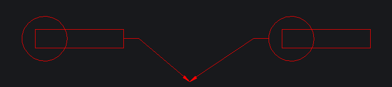
Is it possible to get 2 insertion points in a block placed in a Mleader style to get the possibility to switch from the Mleader properties dialog box ? My block is non symetrical and I don't how to handle it with a Mleader. See attached illustration.
Comments
-
Not sure what your after, in a mleader is all sorts of info about points of a mleader, if you know scale of block and its insertion point can work out a second point. Your image does not show any points so no idea. Use just that POINT and PDMODE 34, to show points you want.
0 -
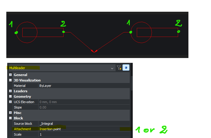
Here you will find attached a new pic to illustrate the behaviour I expect.
The block (as content of the Mleader) does contain 2 instertion points. I wish I could switch from one to the other in the Attachement property of the Mleader.
0 -
For this type of question it is always best to post a sample dwg. it should be possible to say make a simple lisp to swap the two points. need the dwg to see the second point.
0 -
Hi Alanh,
Here you will find enclosed a dwg containing a Mealeader (with block as content). I wish I could choose the Mleader attachment point at the left side of the block (initial insertion point) or the right side (I cannot define). Any Idea would be appreciated very much. TY
0 -
Hello.
It is not possible to have two insertion points in a block.
One approach that could be useful is like this:
- Use Center extents as attachment instead of Insertion point.
- Add some geometry to the block to encompass the existing one.
With these settings, the block is positioned to the left or right, depending on how the leader is drawn.
A minimum length of the leader seems to be required in order for this to work.
If the new geometry in inconvenient, then it could be hidden some way.
An alternative could be to place it on a layer and turn that layer off.
Another one could be to use a certain type of line.
I attached a drawing with these settings:
- The geometry is an ellipse.
- The line type is DOT.
- The line type scale is 10 - this is to draw the dots as distant as possible.
With these settings, the ellipse is not visible, but it is there.
And the block is placed to the right or left, depending on the leader's placement.0 -
Hello,
While I admittedly have no clue why the multileader changes its behavior when geometry is added to the source block (in addition to the existing line), you could try another approach: set the landing distance to half the length of your line (i.e., 26.5 mm) and use center extends as attachment, as already suggested by Virgil.
See the attached screenshot of the properties.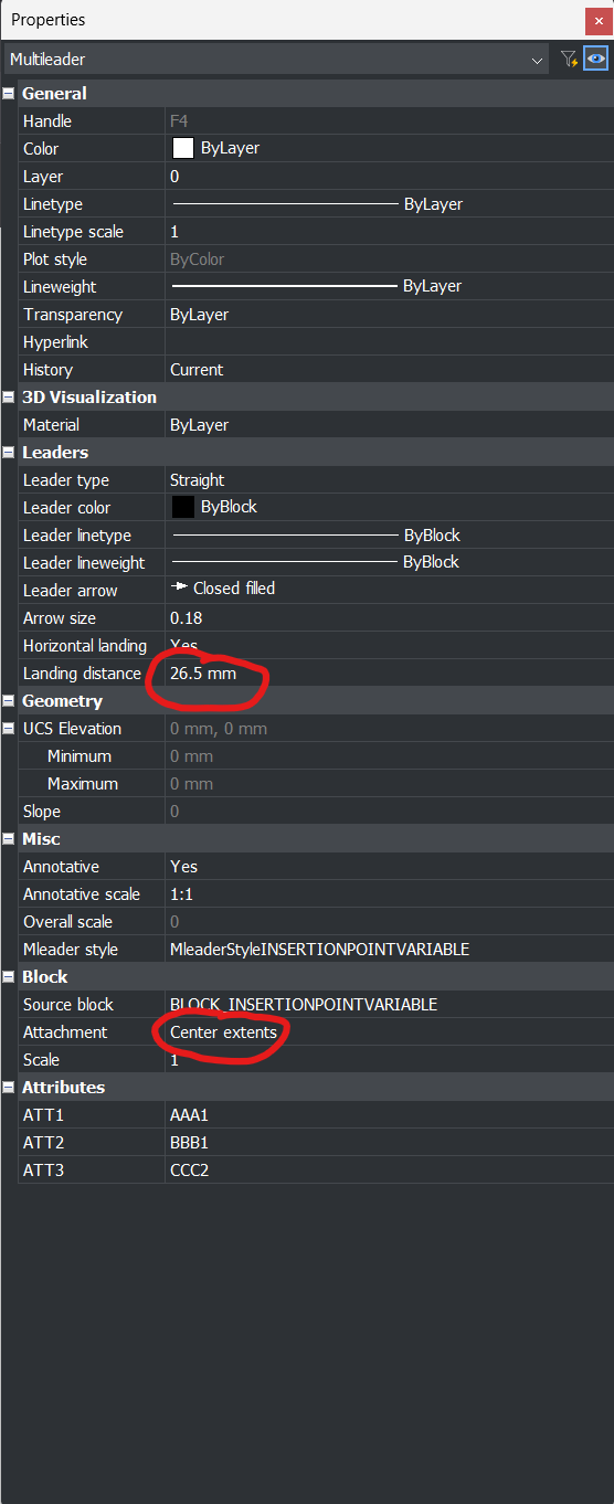 0
0
