Developing a parametric wardrobe generator using AutoLISP — looking for feedback Body:

Hello fellow developers,
I’m working on a project to automate custom wardrobe and cabinetry design in BricsCAD, built primarily using AutoLISP. The goal is to create a robust, parametric tool that generates customizable furniture assemblies, handles internal partitioning, and outputs precise geometry for manufacturing.
Since the LISP community here has incredible experience with CAD automation, I’d love to ask a few technical questions or spark a discussion:
- For those handling complex parametric generation via LISP, do you lean more towards standard DCL for UI, or have you found better ways to handle highly dynamic inputs within BricsCAD?
- How do you best manage performance when regenerating multiple complex blocks or 3D solids/regions dynamically?
I would appreciate any tips, architectural advice, or thoughts from anyone who has built similar parametric tools in the past.
Thanks in advance for sharing your experience!
Comments
-
For me I use DCL's. Give these a try they are free to use just ask that you leave my name in code, can be used in any code. There is sample code in each lisp. Just make sure you svae them in a support path location. I have more like 2 column radio buttons.
You can convert a dcl into lisp code, using the RLX program.
Obviously can take advantage of dcl with child dcl's.
Another
Did make a write dcl code from a dwg using blocks to represent the dcl objects.
I should have mentioned I insert a dynamic block and then populate a dcl with the variables you can change, this way your not using question after question or properties to set values.
0 -
As someone who has been down this path before, I would choose another language besides lisp. Eventually, you’re going to want Palettes with Drag and Drop, Jigs, better access to 3D solids, Regions with BRep, external databases etc. C# / .NET is a good choice.
If you insist on Lisp, then OpenDCL is the GOTO for a great looking UI
0 -
Thanks AlanH, this is very useful.
I am currently building a parametric wardrobe/cabinet engine in AutoLISP. At this stage I want to keep the calculation/build logic inside my own central engine, but I can definitely see DCL being useful as an input layer, especially to avoid asking the user question after question in the command line.
I will test your multi radio buttons / toggles / getvals approach as a UI adapter for entering parameters, while keeping the actual geometry rules, validation gates and build logic separate.
Of course, if I use your code or adapt parts of it, I will keep your name in the code as requested.
Do you know if these DCL examples work cleanly in BricsCAD as well, or have you mainly tested them in AutoCAD?
0 -
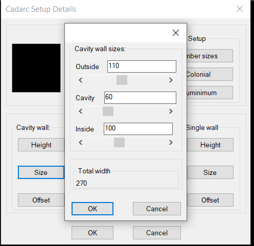
I run 99% Bricscad so yes they work. I use a trick of writing the dcl to a file remove the (vla-delete fname) then use the RLX make lisp code, it takes a little bit of thinking but that is how I make complex dcl's like image above that has getval, radio and toggle. All code in the lisp. Using Sliders can be useful, as shown in the child Dcl.
Using Opendcl is way more powerful and the only reason I don't use for my clients is they have to install the run time, sometimes the end user struggles, biggest problem is their IT, then can be barely able to install lisps.
I have an install method can help with that its based around a lisp and a ZIP file, yes lisp can extract a zip file.
I am not going to go into it but in the house program above all objects are drawn on end user layers, where I worked we had a simple text file with proglayer clientlayer color linetype and some smarts but that will cost you.
If it takes off then a higher level language is worth looking into, the house program is like 130 lisps.
I know using VBA forms is way smarter than dcl's but be wary of VBA.
This cleans your temp directory say of junk dcl's.
 0
0 -
Thanks for sharing these insights and the
cleanuptemp.lsproutine! You hit the nail on the head regarding the real-world deployment of CAD tools.Your point about avoiding OpenDCL and VBA due to user-end IT restrictions is spot on. While OpenDCL is powerful, forcing a runtime installation on a locked-down corporate machine can kill a project before it even starts. Pure LISP/DCL generated on the fly is absolutely bulletproof for deployment.
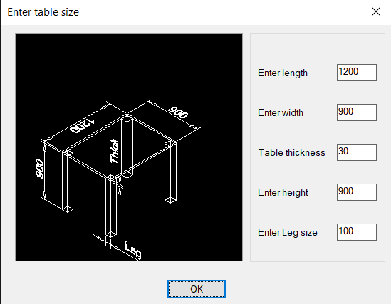
The UI examples you posted look fantastic. The table dialog in
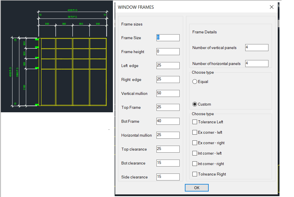
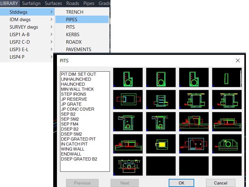
image_48003f.pngshows how clean a native DCL can look with proper image integration, and the grid library inimage_480096.pngis a great reminder of how powerful slide menus can be when handling multiple component variations.The ZIP extraction trick natively via LISP sounds like a brilliant way to package custom toolkits without relying on complex installers. Also, handling client layer mapping through an external text file is the gold standard for professional workflows—it makes total sense that it's a proprietary part of your system.
Really appreciate you showing these examples and sharing your workflow philosophy!
Best regards,
zen
0 -
I agree with Daniels comments. Most developments in this area are done in a way that they aren't tied to any particular CAD platform.
If you're looking to create a LISP solution, then you could look to SOZ-LIVE for inspiration. It takes an object orientated approach to LISP programming, which lends itself to what you're looking to do.
Jason Bourhill
CAD Concepts Ltd
0 -
Hi Jason,
Thank you for your feedback.
I agree with your point about not tying the core development too closely to one CAD platform. In my case, the current implementation is being developed and tested in BricsCAD with AutoLISP, because that is the environment I use in production, but I am trying to keep the furniture logic separate from the CAD-specific drawing layer.
The idea is to keep the wardrobe/joinery rules — modules, drawers, shelves, rods, clearances, variants and validation — as structured data and logic, while the CAD layer only creates, updates and checks the geometry.
Thank you also for pointing me toward SOZ-LIVE. I will study that more carefully, especially the object-oriented approach in LISP. That sounds very relevant to avoiding a large procedural script that becomes difficult to maintain as the system grows.
Best regards,
Zenon0 -
Hi Jason,
Thank you for the recommendation! I actually had a great smile reading your comment because I am the creator and developer behind SOZ-LIVE.
Hearing an industry expert suggest my own framework as a solid example of an object-oriented approach to LISP is the ultimate compliment. It perfectly validates that the architectural philosophy I’ve been building into it is hitting the right notes in the CAD community.
You and Daniel make an excellent point about platform independence. That is exactly why I designed SOZ-LIVE this way—to ensure the core parametric logic can scale and adapt smoothly without being hard-coded to a single environment.
Thanks again for the support and the shout-out to my project!
Best regards,
Zenon0 -
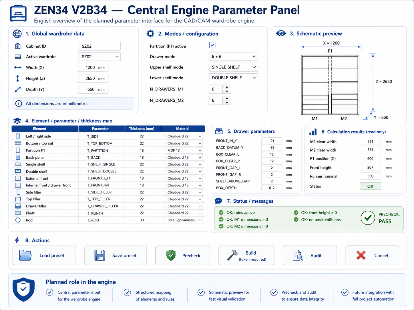
EN V2B34 — Parametric CAD/CAM Furniture Engine — open to custom AutoLISP work
We are building a central parametric CAD/CAM engine for wardrobes, walk-in closets and built-in furniture. Instead of drawing every wardrobe manually, the user changes parameters and the engine rebuilds the 3D model: cabinet body, shelves, drawers, hanging rods, filler panels, plinths and, later, automatic dimensions on layout sheets, plans and sections.
The project is developed in BricsCAD / AutoLISP. The current focus is correct geometry, construction rules, variants, safe rebuilds and a stable central engine. CNC, BOM and cutting lists are planned later.
What the system can control
The model supports wardrobes with or without an internal partition. It can work as an M1 / M2 layout with a P1 partition, or as a full wardrobe without a partition.
The system can change:
- width, height and depth,
- partition on / off,
- single or double shelves,
- automatic or manual shelf positions,
- automatic or manual drawer fronts,
- drawer box depth adjusted to cabinet depth and runners,
- hanging rods under a shelf or positioned manually,
- filler panels and plinths,
- thicknesses of sides, shelves, backs, fronts and other elements.
A key locked rule is:
SHELF_ABOVE_Z1 = highest drawer front Z2 + 30 mm
This rule works for both M1 and M2.
Current stable checkpoint
Current PASS file:
SZ01_MASTER_V2B34_V8_V12_MASTER_V26E_FIXB_REKA_AUTO_MIX_POLKA_ZAWSZE_30_PASS.dwg
This file has DBMOD = 0 and is the current rollback point.
Confirmed in this checkpoint:
- M1 shelf above drawers: highest drawer Z2 = 472, shelf Z1 = 502, gap = 30 mm,
- M2 shelf above drawers: highest drawer Z2 = 732, shelf Z1 = 762, gap = 30 mm,
- 6 drawer fronts,
- 12 drawer box sides,
- 6 drawer bottoms,
- 6 drawer backs,
- 2 shelves above drawers,
- 8 ordinary shelves,
- 2 hanging rods,
- 4 drawer-side filler panels,
- 4 support bases,
- 4 internal side panels,
- P1, BCT, SZ02 and SZ03 protected.
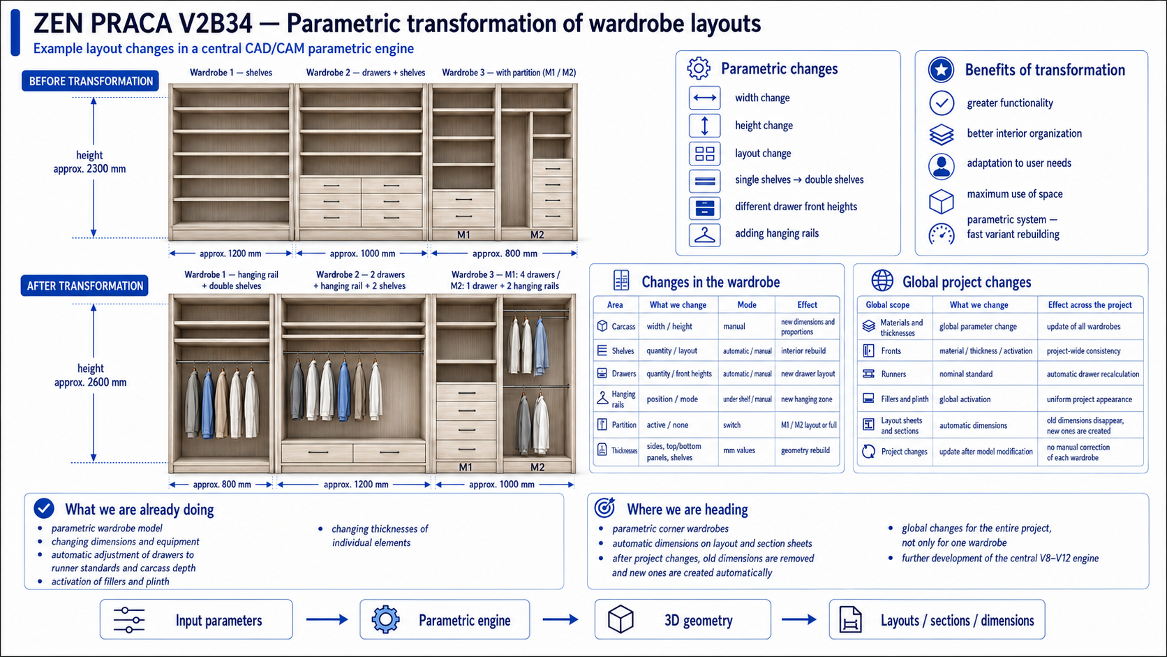
Project demonstration
The system can show three wardrobes standing next to each other in one built-in wall. After changing parameters, the same wall can rebuild with different widths, heights and internal layouts.
Example:
- before: height about 2300 mm, widths 1200 / 1000 / 800 mm,
- after: height about 2600 mm, widths 800 / 1200 / 1000 mm.
The transformation can change lower shelves into a hanging rod, replace single shelves with double shelves, change drawer quantity, use different drawer front heights, and add rods in different modes.
This is not manual redrawing. The goal is: change parameters, rebuild the model.
Single wardrobe parameter table
Area
Change
Mode
Result
Cabinet body
width, height, depth
manual / preset
new overall size
Partition
on / off
switch
M1/M2 or full wardrobe
Shelves
quantity, height, type
automatic / manual
rebuilt shelf layout
Double shelves
on / off
automatic / manual
double shelf system
Drawers
quantity, front heights
automatic / manual
rebuilt drawer package
Shelf above drawers
position
rule-based
always 30 mm above top drawer
Rods
position
under shelf / manual
hanging zone
Filler panels
on / off, width
switch / value
side package update
Plinth
on / off, height
switch / value
base update
Thicknesses
boards, backs, fronts
mm values
geometry rebuild
Runners
nominal standard
automatic
drawer depth adjustment
Planned global changes
Global scope
Change
Project-wide effect
Materials and thicknesses
board and element parameters
update all wardrobes
Fronts
material, thickness, type
consistent design
Runners
nominal standard
drawer depths recalculated
Fillers and plinths
global on / off
consistent built-in layout
Shelves
single / double
shelf systems rebuilt
Drawers
quantity and front heights
drawer packages rebuilt
Rods
under shelf / manual
hanging zones rebuilt
Layout sheets
automatic dimensions
old dimensions removed, new ones created
Whole project
multiple wardrobes at once
global control, not one wardrobe only
Next plans
Next we will run operator-input tests: the LSP asks for values, the user enters real parameters, and the engine validates the result. This will test manual drawer heights, manual shelf positions, automatic shelves, rods, dimension changes and the locked 30 mm shelf-above-drawers rule.
After M1/M2 tests, we plan to transfer the same logic to a fresh FULL wardrobe without a partition. Later we want global changes for the whole project and automatic dimensions in layouts, plans and sections.
Future expansion
The engine may later support:
- kitchen furniture,
- internal doors,
- decorative wall panels,
- wall panels with mirrors,
- wardrobe fronts with aluminium frame + glass,
- wardrobe fronts with aluminium frame + mirror,
- routed fronts and other front systems.
The goal is one central parametric engine, not separate scripts for every product type.
Final direction
We are building a V8–V12 central engine for parametric wardrobes and furniture built-ins. A parameter change should rebuild the model, not require manual drawing repair. This is the foundation for wardrobes, walk-in closets, full wardrobes, partitioned wardrobes, corner wardrobes, kitchens, doors, wall panels and front systems.
 0
0


