Need insight on dealing with drawings from another CAD program

Got some drawings from a customer who uses Creo and units are millimeters. This is a challenge for me since I'm a "old school draftsman" and not experienced in switching units, dimstyles, fonts and etc. The drawings are in DWG format but come in rough with fonts missing, scales all over the place, more layers than I ever use.
Basically to save time I've been doing just touch up work where needed, checking dimensions making sure they're not corrupted by the translation process. Can someone recommend a work flow for this sort of process? Do I make a new template for millimeters, dimstyles and etc. then copy/paste the 2D entities only then recreate the dimensions, notes and other info?
Know this is a loaded question but would like to hear from others so any comments would be most welcome!
Comments
-
I don't think recreating is the way to go. Its a bit hard to make suggestions without some idea of what is wrong. If the dims are correct is it a case of changing dim style, or maybe just dimscale and a dim update.
Can you post a few bits out of a dwg that are a problem with say a before and after.
Don't know what you mean by scales are wrong.
1 -
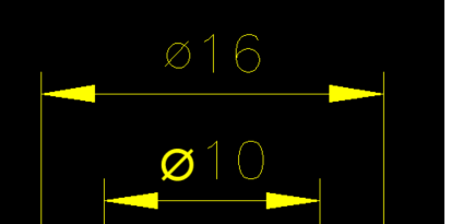
I attached a simple drawing; sample-1 is before, sample-2 is after inserting it into my standard template.
Dimensions are correct except no diameter symbols. If I add new dimensions they are way off due to me not having a mm dim style. Do I use my current template and just change the linear dimscale to suit mm and/or also insertion units under general settings?
The scales can differ depending on the drawing, some 2:1, 17:100, 1:2 etc. What's strange is some of these drawings only have entities in paper space not model space. Thanks for chiming in!
0 -
Ok, finally got them attached.
0 -
The dia symbol appeared for me, if you look at the dim though it's using a special character.
{\fSymbol_ASME;\W1.0;⌀}<>
It is possible to replace the {\fSymbol_ASME;\W1.0;⌀} with say correct dia symbol. It may be as simple as %%C<> You need a lisp etc.
Do you know anything about lisp ?
In image I manually changed the 16.
 0
0 -
Symbol_ASME is the font, like GD&T. no need to change the dimension text, just make sure you have the fonts installed. you may run into a symbol that’s not easily replaced with a built-in code (i.e %%C, %%D)
The table (title block) is in bad shape though, as soon as you touch it, it recomputes. I don’t know if it would be easier to replace it with your own title block. Maybe just explode it
0 -
Yes manual editing is what I'm doing now, it's slow but all things considered it could be worst like redrawing completely from scratch. One thing that keeps occurring with these drawings is a pop up message saying the font "Triumbi" being replaced by standard font. Tried looking up the missing font but it appears to be only available from Creo.
0 -
Thanks ALANH, played around with lisps a bit mainly editing to suit. Could probably google something that might be workable.
0 -
Try this
(defun c:putdia ( / obj ss)
(setq ss (ssget "x" (list (cons 0 "DIM*")(cons 410 (getvar 'ctab)))))
(if (= ss nil)
(progn (alert "You did not selected any dimensions will now exit ")(exit))
(progn
(repeat (setq x (sslength ss))
(setq obj (vlax-ename->vla-object (ssname ss (setq x (- x 1)))))
(vlax-put obj 'textoverride "%%C<>")
)
)
)
(princ)
)0 -
I totally get where you’re coming from — working with translated drawings from different CAD platforms can be a real headache, especially when units, fonts, and layers don’t match your usual standards. I’ve run into this a lot, so here’s a workflow that’s helped me keep things clean and consistent:
Make a Clean Template
Yes — creating a dedicated template for metric work (millimeters) is a solid idea. Set up your preferred dimstyles, text styles, layers, and units in that template. It saves time in the long run and helps avoid repeated setup every time you get new files.Use WBLOCK or COPYBASE
When you get the customer’s DWG, open it, clean out any unnecessary junk, then WBLOCK (Write Block) or COPYBASE just the geometry you need into your clean template. This helps get rid of unused layers, styles, or odd settings that sneak in during file translation.Recreate Critical Annotations
I’d recommend recreating dimensions and notes in your own dimstyles and fonts when possible. This ensures they’re accurate, look consistent, and won’t cause problems down the line. If the original dims look okay, double-check them with your own dimension checks to be safe.Manage Missing Fonts
If the fonts are missing, swap them out with your standard ones. It’s better to have consistent, supported fonts than to chase down obscure ones every time.Audit & Purge
Before saving your cleaned-up file, always AUDIT and PURGE to clear any leftover clutter.I know this takes a bit more time upfront, but it really pays off for repeat jobs and keeps your files tidy and reliable.
Thanks,
Reetie2 -
Like Reetie, we had a lisp that did various things, linetypes, layers and so forth. I have given you one function. The post above gives you more ideas.
0 -
Thanks ALANH, do you use regular notepad or notepad++ to cut/paste lisps?
0 -
Thank you Reetie for the outline that will help. Regarding a template I'm not sure which settings I need to tweak for millimeters so being a visual learner I'll see what I can find on youtube. I'm on a tight deadline for this current project as the PO is about to drop so refining the workflow will have to wait till things slow down a bit.
0 -
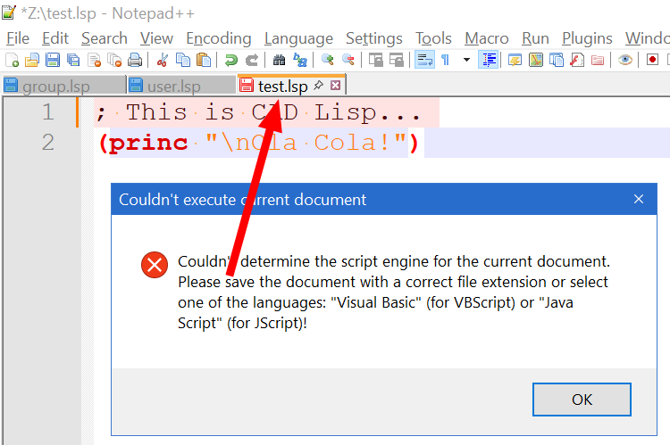
I use Notepad++ to write code, youn can set language to lisp so it shows open closed brackets and so on very easy to check code. It has a option to run code from N++ but it seems to only work with Acad. It was a real handy option. I did contact via Github to see if could get a Bricscad version. They said should work.
Re setvars you can compare two dwg dumps using compare option of two files. It has autocomplete.
0 -
Interesting @Alanh , can you elaborate in that? By the way, with thanks to Torsten Moses I created a highlighter ( ) some time ago.
0 -
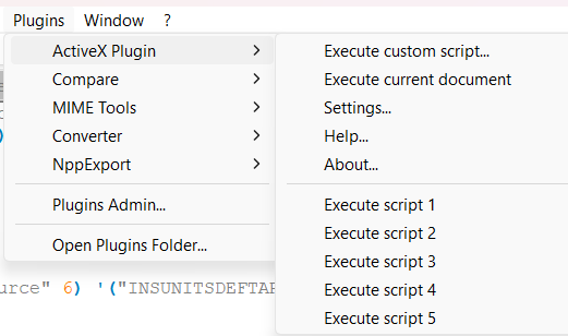
Wiebe van der Worp very interesting, have you tried the Active X plugin I am not sure if it was a N++ upgrade or it only works with Acad, its a great function as you can run code direct from N++ but can not get it to run in Bricscad.
 0
0 -
states it is not functioning in BricsCAD. A bit of a pity but pasting on the command line and or (load …) with cursor action to repeat execution works okay for me.
 0
0 -
I am BIGAL at Cadtutor, I did post on Github about problem but did not get any real answers about running code from N++ with Bricscad, yes I do cut and paste at moment. been coding for over 40 years. I may look into it again.
0 -
I teach AutoCAD, and the issue of units is certainly a confusing one. Originally, AutoCAD was unitless. And while you might create a dimension style that puts a " or mm after the value, that is just adding text to dimensions. A line that is 10 units long might still have been intended to be 10 inches, 10 lightyears, 10 miles, etc.
Eventually AutoCAD did get a new variable they called "Insertion units". Though the user can just ignore it, and leave the drawing unitless. When a drawing is inserted into another, the receiving drawing reads the "insertion units" and will then scale the drawing to match with whatever Insertion Units are set in the receiving drawing.
Your drawing may not have "insertion units" set. So, I suggest first opening that drawing, and then setting it to be the units that the source intended. Then, after purging that drawing, I would insert that drawing into your own drawing, which must have its own insertion units set.
-Joe
0


