more info about Kinematic Analysis

Hello,
is there some more detailed info, besides a youtube film and some pages in the Bricscad V17 user guide ? I mean some more examples ? In my drawing i have movement in a sloted hole. That means that a axle/ bolt kan slide between two points. And i want to learn how i can use the program to prededict movement.
anybody got some experience ?
Greeting Theo
Comments
-
Your example model is missing the components. You need to either ETRANSMIT the model, or switch all the components to local from the mechanical browser.
Attach an example of a simple scissor mechanism, which can be driven by a height parameter. There is also a Lift example included with the BricsCAD install, look in the samples folder.
Regards,
Jason Bourhill
CAD Concepts0 -
Oke Jason,
thank yoy for your reply. I am goning to look at your sample. and i am gonna do some research about the therms that you use, because i dont know what they mean haha.
0 -
@Jason Bourhill said:
Your example model is missing the components. You need to either ETRANSMIT the model, or switch all the components to local from the mechanical browser.Attach an example of a simple scissor mechanism, which can be driven by a height parameter. There is also a Lift example included with the BricsCAD install, look in the samples folder.
Regards,
Jason Bourhill
CAD ConceptsHello Jason,
How can i build a paramater like that? In your file i only can adjust height between 500 and 2450.
Regards,
Jeroen
0 -
Hi Jason
See if this is what your looking for...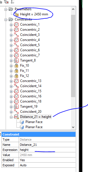
As far as I noticed there's no "limits" that can be imposed in Briscad, like the motion range available in some other softwares.
Unless the constraints itself.
In this example file we can had whatever value, not just 500~2450.
Cheers0 -
@crpt2008:
You can use functions in expressions. With the min and max functions you can recalculate a parameter value and in that way limit its range.0 -
Top tip Roy.
Totally neglected that idea. ;-)0 -
Top tip Roy.
Totally neglected that idea.") 0
0 -
Sorry for the double post.
My browser was not updating0 -
@Roy Klein Gebbinck said:
@crpt2008:
You can use functions in expressions. With the min and max functions you can recalculate a parameter value and in that way limit its range.Top tip Roy!! So glad that someone takes the time to drill through the HELP to highlight these options :-)
Attach a revised version of the Scissor Lift model utilising Roy's advice to limit the range of movement between 500 - 2450mm. The screengrab shows the how I set my parameter up to do this.
Regards,
Jason Bourhill
CAD Concepts0 -
Hi Jason,
Thanks for your help. It's going the right way with my mech arm. Only the arm need to slide or stop at some points during the movement. A bit hard to explain so i added the file and a screenshot. Hope you can help.
Kind regards,
Jeroen
(All rights reserved for the design)
0 -
Also another question. Is is possible to make it moving and make an videofile of it?
Kind Regards,
Jeroen
0 -
@jeroenvds said:
Only the arm need to slide or stop at some points during the movement. A bit hard to explain so i added the file and a screenshot.Even with the file it's hard to interpret what you want to achieve. The following tips hopefully may help:
Try using a Helper solid/component to constrain the arm's movement in the manner that you want. This helper solid can be put on a hidden layer so it doesn't display.
In V18 you can now constrain to UCS, which can reduce the need to use helper solids.
You can constrain to 2D entities, such as LINEs and CIRCLEs.
Regards,
Jason Bourhill
CAD Concepts0 -
To first answer your previous question:
I don't think it is possible for a solid to behave as a sort of 'door stopper constraint'. To model this behavior you will probably have to rely on expressions and perhaps hidden solids.To animate 3D constraints you can use a script. And with screen capture tools you can create a video of such an animation. See the attached files (I had to change the '.scr' extension to '.txt'). I have used ShareX to create the MP4. For a slower animation call the _Delay command after every parameter change in the script.
BTW:
To control the lateral movement of the elements of the scissor mechanism I would use a single Rigid Set constraint.0 -
@jeroenvds said:
Also another question. Is is possible to make it moving and make an videofile of it?Kind Regards,
Jeroen
ANIPATH allows you to create a flythrough video of a scene, but it won't allow you to animate the part.
You can create a SCRIPT that utilises -PARAMETERS to move the part, then to generate a RENDER image after each movement. There are applications that will convert a series of images together to create a video.
Regards,
Jason Bourhill
CAD Concepts0 -
@Roy Klein Gebbinck said:
@jeroenvds:To first answer your previous question:
I don't think it is possible for a solid to behave as a sort of 'door stopper constraint'. To model this behavior you will probably have to rely on expressions and perhaps hidden solids.To animate 3D constraints you can use a script. And with screen capture tools you can create a video of such an animation. See the attached files (I had to change the '.scr' extension to '.txt'). I have used ShareX to create the MP4. For a slower animation call the _Delay command after every parameter change in the script.
BTW:
To control the lateral movement of the elements of the scissor mechanism I would use a single Rigid Set constraint.Thanks for your help. This helped alot!
One morge question. When i make a render de arrows of the ucs are still visible. Can you tell how i can turn this off?
Greetings,
Jeroen
0 -
@Jason Bourhill said:
@jeroenvds said:
Only the arm need to slide or stop at some points during the movement. A bit hard to explain so i added the file and a screenshot.Even with the file it's hard to interpret what you want to achieve. The following tips hopefully may help:
Try using a Helper solid/component to constrain the arm's movement in the manner that you want. This helper solid can be put on a hidden layer so it doesn't display.
In V18 you can now constrain to UCS, which can reduce the need to use helper solids.
You can constrain to 2D entities, such as LINEs and CIRCLEs.
Regards,
Jason Bourhill
CAD ConceptsThanks for your help!
Greetings,
Jeroen
0 -
To hide/display the UCS icon you can use the _UscIcon command.
0

