Extruding smooth 2d object to 3d: increase polygon count

When I attempt to extrude smooth 2d objects into 3d, the polygon count can be rather low. The issue persists even after entering 'regenall' and increasing viewres to 20000.
Is there any way to increase the polygon count before/after extruding?
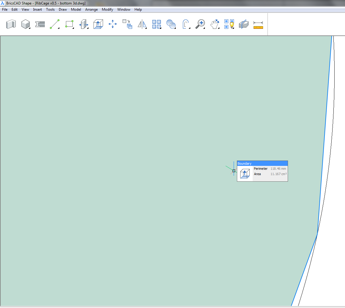
See attached pic for the issue (it shows a close up of a circle edge, and, in pale green, the area that will actually be extruded upwards/downwards to create the 3d solid)
Searched everywhere and cannot find an answer, but apologies if this has been addressed.
Comments
-
There is somewhere a setting in settings to adjust arc resolution.
Unfortunately I already forgot where it was.
I had it looking better but lost it again with installing a newer version.
So I have to search for it first ....But that default setting doesn't look good at all.
If for any reasons curved elements can display as Polygons only, that
would be ok. But edgy for 3D beside real Circles for 2D is irritating.
It looks ok in 2D Wireframe but ugly in standard wireframe mode.I first realized that with rounded Walls.
Beside looking polygonal itself, butted Wall connections or inserted
objects look really bad in top views.
It doesn't look much so but I think the snap works correctly though.But as e.g. rounded Walls + some Walls when linear connected to it
show incorrect thicknesses I am not so sure if geometry calculations
really work mathematically or more like it looks on screen.0 -
Not sure if is the right setting but
FACETRES (activated by default ?) and setting the number from 0.1 to 0.5
seems to make circles look better.
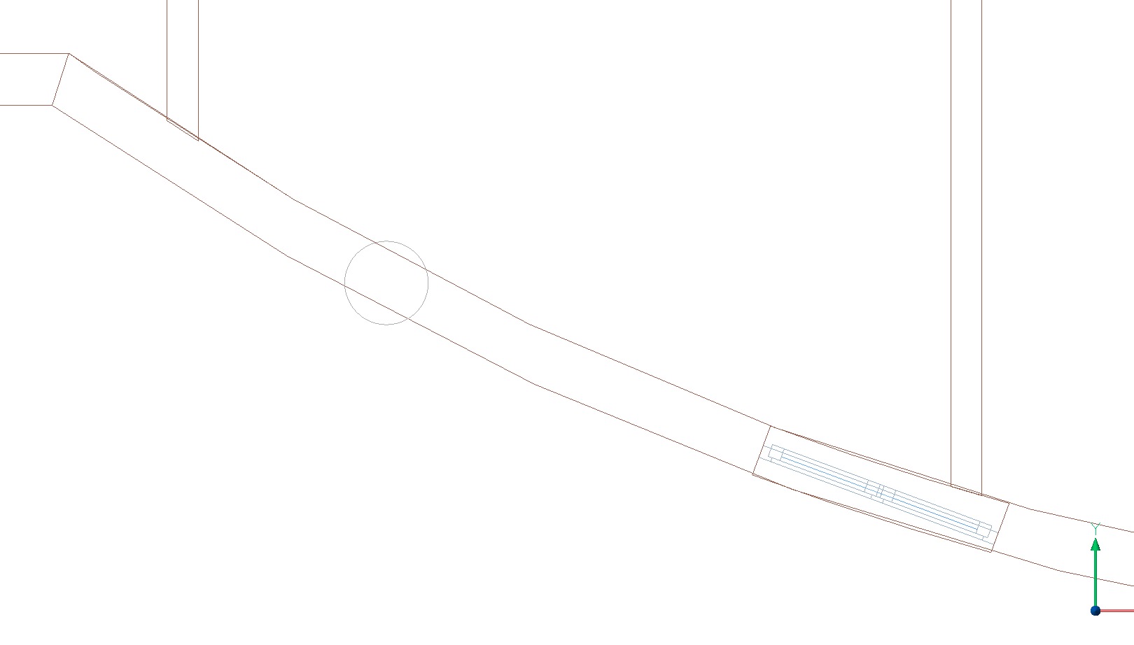
(Unfortunately not my rounded Walls)Added an example screenshot.
Wireframe, slightly rotated from top view + real top view.
a cylindrical Column on the left
(looks ok by that 0.5 setting)
my rounded Wall
(these vertical lines appear on the real circle and not meeting the horizontal
polygonal edges and their vertices (?))
inserted Window and a butted Wall.
Window was later moved to the side to check if its angle will adapt
to the rounded Wall - no.
 0
0 -
I don't have shape. But in Brics CAD, use the "Facet resolution" option in the settings under Modeller properties under modeller.
ie: Program options - > Modeler -> Modeller properties... -> Facet resolution
You can crank it up past 0.5. I just put mine up to 5.0. But it will affect performance.
0 -
Oh, again,
this time I looked if not in Shape sub forum.
But you can see at the screenshot that it is about Shape.
... I missed Shape - no settings there.0 -
Sorry-I should have made clear-I am using Bricscad Shape.
No Facetres option available!
Anything else I can try?
Thanks for the help all the same.
0 -
In a bid to simplify the user interface Bricsys has opted to not expose the settings in Shape. Quite a few settings however, including FACETRES, are stored in the drawing. And, this may be unexpected, Shape does obey these settings (tested with Shape V18.2.06). So one way to solve this is to open your drawings and templates in a 'Full' version of BricsCAD and change the FACETRES setting there.
But keep in mind that the FACETRES setting only influences the graphical representation of objects. When you extrude a circle it will produce a 'true' cylinder.
0 -
Thanks Roy-unfortunately the extrusion really does seem to be tied to the polygon count of the highlighted outline. See attached pictures.
Unfortunately I have no access to the full version of bricscad at the moment, although I'll see if I can download it (subject to budget, unless there's a demo version?)
Thanks to everyone for the help so far.
0 -
Yes, you can load a demo, download is directly on the website.
@Roy Klein Gebbinck
Are these settings stored in the file ?
I think it is globally in the Programm Settings.And there are a few more settings beside FACETRES that may impact
rounded Solids other than Circles.0 -
@yamax87:
To verify what I have said, try rotating a cylinder and check if the facets rotate as well. Or try snapping to the corners of the polygonal representation.@Michael Mayer:
The _Settings dialog clearly specifies which setting are stored in the dwg and which are not.0 -
Yes, and for me related settings happen in "program options" and
not in "drawing", which makes them global which I think makes sense.
That's why I asked0 -
Dear Michael,
several settings are shown multiple times, in Settings dialog ... the Settings dialog visualises all the settings, hence several settings can appear in multiple sections.
Simply search for "Facetres" ... and continue the search.The type and storage of a setting is shown at left bottom - the section(s) where a setting is visualised have no relations to storage place.
So yes, FACETRES is "per-drawing" - and this makes sense, as Facetres can depend on extents, particular content and more.many greetings !
0 -
How about that for a coincidence.
A client called up and asked me to send his model to him in .stl format so he could print it in 3D.
Here is the difference between FACETRES set to 10 and FACETRES set to 1.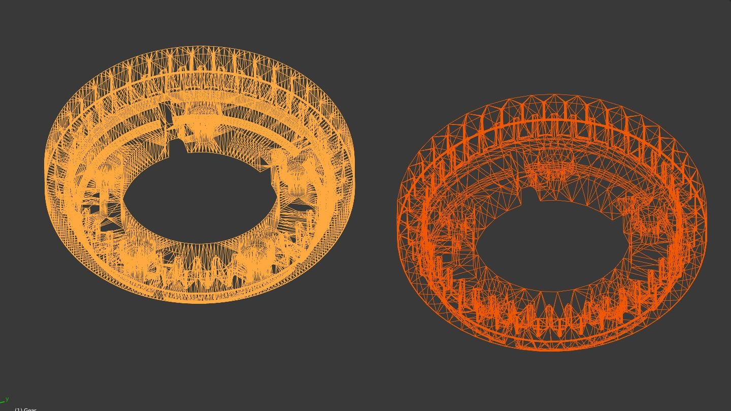 0
0 -
@DFLY:
This may be of interest:
https://forum.bricsys.com/discussion/24343/how-to-increase-resolution-of-stl-export0 -
Thanks a lot Torsten.
@Torsten Moses said:
Dear Michael,several settings are shown multiple times, in Settings dialog ... the Settings dialog visualises all the settings, hence several settings can appear in multiple sections.
Yes, I realized that when starting with Bricscad and am still not sure if I like that.
Simply search for "Facetres" ... and continue the search.
The type and storage of a setting is shown at left bottom - the section(s) where a setting is visualised have no relations to storage place.OK, haven't thought about this and will care more ....
So yes, FACETRES is "per-drawing" - and this makes sense, as Facetres can depend on extents, particular content and more.
many greetings !
OK, I looked closely.
I was confused as the Setting resides only in the "Program options" section
of the Settings tree and the first search result for FACETRES = "ddUseFacetRES",
to activate the whole thing,
shows "Preference" as its location.
But as stated, the FACETRES itself shows "Drawing".So I wouldn't have expected that to be a "by File" variable ever.
But as I trust @Roy Klein Gebbinck much more than myself in these things,
I asked.a)
So why doesn't that FACETRES setting at least is also (or only) showing in
"Drawing" Settings Section ?b)
Why isn't that a global "Preference" Setting,
when set by a inconvenient low res default is annoying in any drawing ?c)
I would expect that for certain dense special project where you may
want to lower such setting to avoid lags when working,
there would be an option in the Drawing Settings to just overwrite that
Setting for such files only.
(like FACETRESLOCAL)So is the the recommended way of using such Settings by setting
custom File Templates ?BTW,
why don't exist the min/max values
(0.01 - 10 as I learned from the other thread linked)
in the description/tool tip ?0 -
@Roy Klein Gebbinck said:
@DFLY:
This may be of interest:
https://forum.bricsys.com/discussion/24343/how-to-increase-resolution-of-stl-exportThanks. I tried spaSurfaceTol=0.005 vs Facetres = 10 and yes , you can see spaSurfaceTol = 0.005 is better.
But a word to the wise. Read the linked discussion, as I think you have to turn off facetres first.
That is really worth knowing.
0 -
Ok for now I'm just using draftsight (different software) to modify the facetres settings. Seems to work ok but I cannot think for the life of me why they didn't include a facetres modification tool in Shape.
@Roy Klein Gebbinck the facets rotate when the cylinder is rotated...I'm guessing that means the '3d representation' is the true resolution of the shape as stored within Shape?
Thanks for all the replies so far.
0 -
@yamax87:
Please disregard my comment about rotating the cylinder. You are right: the facets do rotate. I must have used very specific angles in my test.To verify that the cylinder is not faceted:
- Check if you can snap to the corners of the polygonal representation (already mentioned).
- _Explode the solid. This results in two regions and one surface. _Explode these new entities. You now have 4 circles.
- Insert a drawing with an apparently 'faceted' cylinder in a drawing where you have changed the FACETRES setting.
0
