Using Linux BricsCAD InPower Ver. 0.97.28 to Simulate Electrical Ground Faults

A small report to show progress,
Grounded WYE DELTA transformers can provide a path for zero sequence currents due to voltage being present at the transformer terminals during a fault. The transformer terminal voltage drives the zero sequence current to the fault. Protective relay devices, set for current magnitude only, can open the transformer circuits causing nuisance power outages. BriscCAD InPower is used to solve this problem. The one line diagram is created and the network simulation is run in BriscCAD InPower.
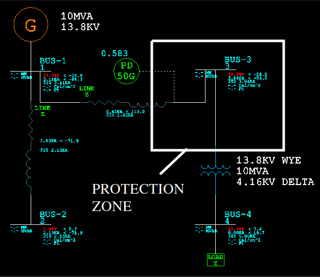
Figure 1. Ground Fault At Bus–2
The one line diagram in figure 1 shows the BicsCAD InPower simulation and the Line “Bus-1 to Bus-3” branch currents with a ground fault at Bus-2. Reference the inpower.out file for additional information. Zero sequence current is flowing from the 10MVA transformer to the fault at Bus-2.
Zero Sequence Data: Branch Current Bus-1->3 = 3.0 * If0 = 1215.0 Amps < 113.170 Deg.
The ground fault protective device, PD 50G, shown in figure 1, has a pick up current value of 250 amps and an operation time of 0.583 seconds with a fault at Bus-2. PD 50G is set to pick up on current magnitude only. This causes an outage at LOAD Z for a fault at Bus-2. The fault is outside of the desired protection zone shown in Figure 1.
One solution for this out of zone outage is to provide a directional ground over-current element that considers both magnitude and the phase of the fault current flowing from Bus-1 to Bus-3.
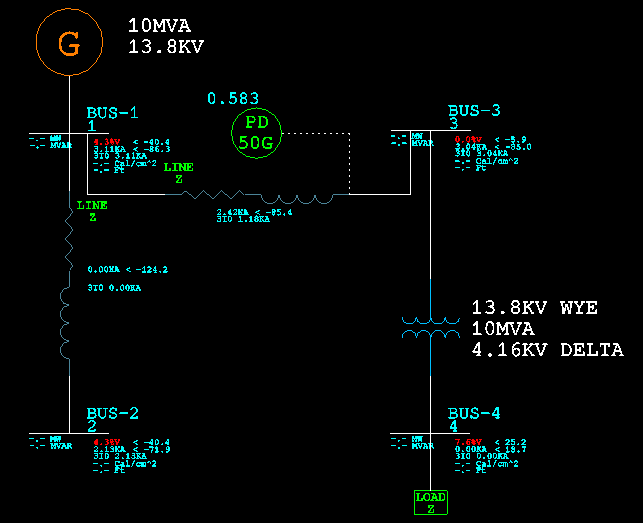
Figure 2. Ground Fault At Bus-3
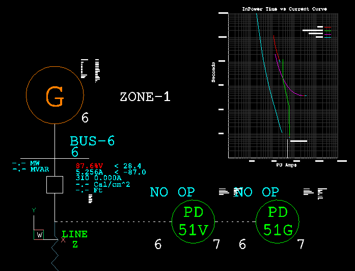
Figure 2 shows the BicsCAD InPower simulation branch currents for a ground fault at Bus-3 inside the protection zone.
Data: Branch Current Bus-1->3 = 3.0 * If0 = 1173.0 < -87.5 degrees. This is current flowing towards the 10MVA transformer.
The angle of the current is -87.5 degrees. The relay fault directional element is set to pick up on any fault with an angle of -87.5 plus or minus 90.0 degrees. Or -87.5 + 90 = 2.5 to -87.5 - 90 = -177.5
Figure 3 shows the BicsCAD InPower simulation after setting the directional attributes. “NO OP“ no operation is displayed at the PD 50G device. The directional relay prevents the loss of power to LOAD Z for a fault at Bus-2. Problem solved with BricsCAD InPower.
Data: Branch Current Bus-1->3 = 3.0 * If0 = 1215.0 Amps < 113.170 Deg.
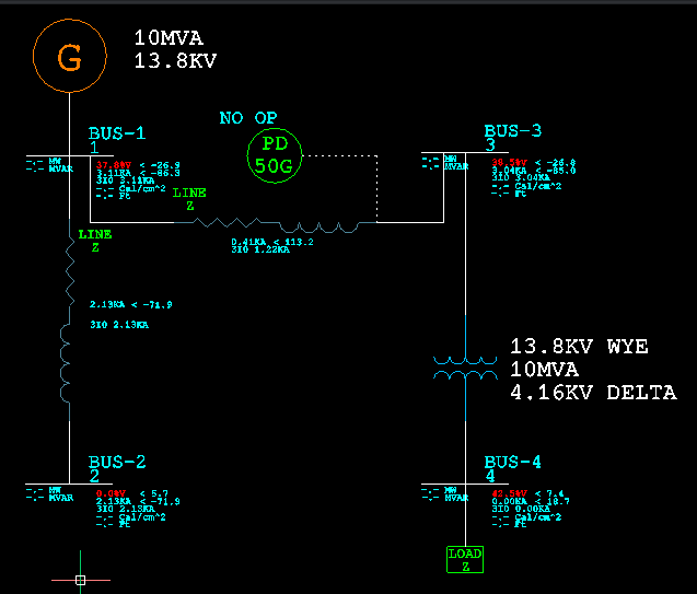
Figure 3. Ground Fault At Bus-2 Directional Relay Setting
Figure 4 shows the settings attributes for the protective relay device PD 50G.
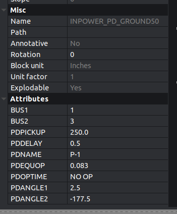
Figure 4. P-1 Relay Settings
BricsCAD InPower is used to solve real world electrical engineering problems. BricsCAD is used to draw the one line and document the electrical network. InPower is used to for the electrical short circuit, power flow and arc flash simulations.
Comments
-
If anyone knows and easy way to reorder block attributes, I would thank you in advance for this information. Some of my blocks have 50 attributes. Recreating these would be an enormous pain.
0 -
Use Bedit if you select a attribute just above is a up and down arrow, press and it moves the attribute order, in Acad use Battorder.
0 -
@ALANH said:
Use Bedit if you select a attribute just above is a up and down arrow, press and it moves the attribute order, in Acad use Battorder.Thanks for the reply, Bedit just brings up the block editor. The attributes are in the order they were created when prompted for user input.
I am wondering if there is a prompt order, re-order of the attributes.
For example, I have a block named Bus, Bus has 18 attributes. The last attribute created was BusName. The user is prompted for the bus name last. I want to move the BusName prompt to the first position so the user is prompted for the BusName attribute first.
Am I missing something in Bedit?
0 -
Try using
BATTMAN. This allows you to change the order of attributes in a block definition, and sync those changes to the inserted blocks.ATTSYNCcan be used separately to sync changes.You may strike limitations if you're using block attributes to store inputs to a programme. Attributes entry doesn't provide validation on the input, Isn't typed, essentially everything is a string. Also doesn't allow for differing units. Alternate options here would be to look at extended entity data, or creating a custom dictionary.
Regards,
Jason Bourhill
BricsCAD V21 Ultimate
CAD Concepts0 -
@Jason Bourhill said:
Try usingBATTMAN. This allows you to change the order of attributes in a block definition, and sync those changes to the inserted blocks.ATTSYNCcan be used separately to sync changes.You may strike limitations if you're using block attributes to store inputs to a programme. Attributes entry doesn't provide validation on the input, Isn't typed, essentially everything is a string. Also doesn't allow for differing units. Alternate options here would be to look at extended entity data, or creating a custom dictionary.
Regards,
Jason Bourhill
BricsCAD V21 Ultimate
CAD ConceptsThanks Jason,
This looks like what I am after. Very nice!0 -
Added a few features to InPower. Up to version 0.97.40
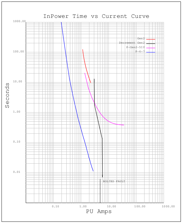
Some of the new features are updated cable models and autogenerated log log time current curves.
pText1 = new AcDbText(yaxisPt, L"Seconds", AcDbObjectId::kNull, 500.0, 0.0);
lyrId="loglogText";
pText1->setLayer(lyrId);
pText1->setHeight(0.20);
pText1->setRotation(90.0*3.14159/180.0);
pBlockTableRecord->appendAcDbEntity(pText1);
wondering how to set the axis text to BOLD?
0 -
@Cnut said:
wondering how to set the axis text to BOLD?Depends on the type of font you're using.
- If it is a .shx font, then bolding would be a defined by pen weight, which in turn is most commonly defined by colour via the .CTB in your print settings.
- If it is a true type font (.ttf), then you would reference the specific .ttf file for bold for that font.
Regards,
Jason Bourhill
BricsCAD V22 Ultimate
CAD Concepts0 -
Thanks for the suggestions, no luck with the pen weights and the fonts. I will try again in the future when I have more time.0

