Paperspace Scaling not correct

I have a drawing of a construction site with a watermains pipe on it. The drawing needs to be to a specific scale as it's for official use and that's the requirement.
My model is in meters and in paperspace the page is in millimetres. For me to obtain a scale of 250mm in my model to 1mm on the page, I have to set the scale as 4:1.
Why is it 4:1 and not 250:1, or even 1:250? Brics can convert meters to millimetres when copying from one model to another, is it just a case that it doesn't convert meters to millimetres from modelspace to paperspace?
Comments
-
Ok the answer is simple. If using a layout and a viewport, with a title block say a A1 at true scale 841x594mm.
The scale factor for the viewport is 1000/250 = 4. You can zoom to any scale in the viewport then go back out and click on viewport then in properties set to 4. All done.Think 1;100 = 10 1:200 = 5.
A side note Acad has a viewport toolbar it has a show current scale so if you just zoom in roghly to what you want you may see 3.123 just type 4 in there and its 1:250. Note if model is mm and layout is mm then divide factor is different.
1 -
I am experiencing the same issue.
Coming form AlanH explanation a scale 1:250 means that a unit on the paper represents 250 unit on the drawing(in any CAD software providing that the drawing was made at a scale 1:1) or 250 on the ground/Site(if you print the drawing on the right paper size).
I have a drawing in meters, and papper space size is an A2 in mm. I set the scale to 1:100(1 paper unit=100 drawing units). When set the scale to that size the drawing gets smaller instead of bigger. The custom scale, when sellecting the viewport is 0.01. I thought I have done something wrong and refered to the training video "Working with annotative entities". Under section "Annotation scaling", starting with minute 2, the user activates the vieport and zooms in untill gets the required size. The custom scale is presented as 0.00547, which corespond approximately to a scale of 1:183. Give that the drawing is a house, that would be the corect way to scale the drawing for printing.
I applied AlanH explanation and I set the custom scale to 10 which, according to BricsCad, coresponds to a standard scale of 100:1(meaning 100 paper units=1drawing unit). This scale is suitable for small elements(i.e mechanical where a small piece needs to be enlarged in order for the details of the drawings to be visible).
Providing that Alan explanation is correct, when I have to print a drawing I always need to make sure that I have to convert the scale shown by Brics cad(100:1) to 1:100 in the Title block. Which to me it does not make any sense.
I am using BricsCad v25.
0 -
Keep the used units in mind… if you are using m in modelspace and mm in paperspace, a scale of 1:1 would mean a scale of 1000 (paperspace mm) = 1 (model m), and 1:100 then gives 1000=100.
But I agree that you should not need to care. Unfortunately, AutoDesk profoundly messed up everything about units in dwg a long time ago, and the world still suffers from that.
Best bet for now is to use scripting to automate these tasks.
0 -
Hello.
As mentioned above, the scales are generic.
They use paper units per drawing units.
In this case mm : m.A solution could be to define a custom template to be used only with meters as units in model space.
This template should contain some scales defined to reflect the real scales.The original scales should be deleted, so that they don't interfere.
For instance, a scale could be named "1:10" and its definition should be 1:0.01.
So, the real scale will be 1 mm : 0.01 m, meaning 1 mm : 10 mm, thus 1:10.The original scale 1:1 can't be deleted, but it can be renamed, to differentiate it from the others.
0 -
Thank you both for the reply. @Virgil solution seems a good option.
So, I have tested with setting the drawing units to millimiters. For context I am working with some GPS coordinates, 9 digits of which 3 are decimals.
When inputed as coordinates CAD does not care they are km, m, mm it just places the points according to the measuring unit of the file.
Starting from Knut's explanation I expected if both ,model and paper, are the same units I could use the proper scale. But again when picking scale 1:100 the drawing gets smaller in paper mode, which to me seems to contradict the expanation.
There is one thing that I cannot find an explanation in plain english of what these 2 setting mean.

As I had them ticked in turns and both, and do not see any change in behaviour.
0 -
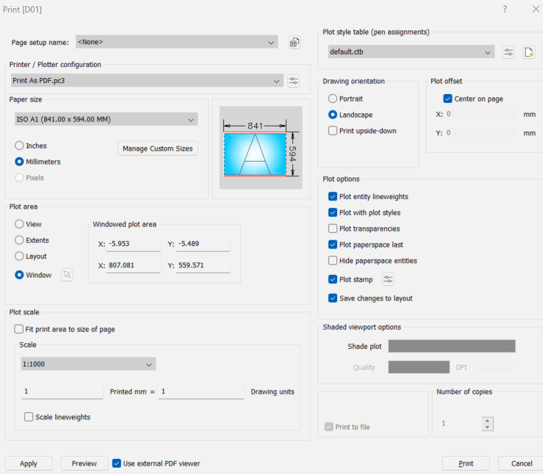
When you use a
-Plotcommand orCPageSetupcommand, you will notice that the dimensions of the paper space are specified in inches or millimetres. The scale at which model space is displayed in layouts, paper space, is based on the following rule: for each drawing unit in the model, a corresponding drawing unit is displayed on paper if the "custom scale" of the viewport is "1".Let's explain this with an example. You have your layout, the paper, labelled as inches or millimetres:
- If you draw in inches in model space, each inch is 1 inch on the paper.
- If you draw in millimetres in model space, each millimetre is 1 millimetre on the paper.
- And if you draw in metres in model space, each metre is 1 millimetre (or 1 inch) on paper.
So it's simple: the "custom scale" of the viewport itself determines how model space units are converted to paper space units. "Custom scale": via
Ctrl-1and selecting the viewport.A custom scale of 2 enlarges what you see in the viewport by a factor of 2, zooming in. A custom scale of 0.1 "enlarges" by 1/10, thus reducing what you see, zooming out.
If you remember that the custom scale is a magnification factor and that the scale is "model units : paper units", you will always figure it out.
0 -
All I can say is we have been doing this method for over 20 years and alway works. Two things may be causing it to not work, our tittle block in a layout for say A2 as requested if we measured the title sheet it would be close to 594x420 units. So longest side is 594 when using "DI" distance 2 points, if you set title block to 0.594x0.420 can see problems. The tile block is plotted at a scale of 1:1 The viewport is scaled to suit, ie 1:250.
just a side note in the plot parameters we had a A1 sheet as our normal title block, at true size 841x594, if when plotting the we set the scale to 1=2 then it would plot a A3 sheet. We used a window setting picking the two diagonal corners.
You are using layouts with viewports ?
0 -
When working with scales you need to consider the units
Model space will be user defined & Paper space will be mm
Note: When working in Meters you have to remember that your Paper space is in Millimeters
& because 1m = 1000mm - use that to determine your scale.
Note: When working in Millimeters you have to remember that your Paper space is Millimeters as well,
This simplifies everything 1mm = 1mm - use that to determine your scale.
E.g. In Meters
I am looking for the following scales (1:100, 1:500) see below calculation:
1000 ÷ 100 = 10 ∴ your standard scale will display 10:1 & custom scale will display 10
1000 ÷ 500 = 2 ∴ your standard scale will display 2:1 & custom scale will display 2
E.g. In millimeters
I am looking for the following scales (1:100, 1:500) see below calculation:
1 ÷ 100 = 0.01 ∴ your standard scale will display 1:100 & custom scale will display 0.01
1 ÷ 500 = 0.002 ∴ your standard scale will display 2:1 & custom scale will display 0.002
Note: if your standard scale displays “custom” this means it’s an annotation scale not created,
Then proceed to create the annotation scale & your scale will appear.
At the end you can print the DWG out and measure to test if your scale's are correct, what you measure times your scale should give you the drawings measured length or yous a scale ruler
Hope this helps
1 -
Paperspace units are always mm. With Insunits = meters (which applies to modelspace only), a 250mm line is really 1/4 meter long. To print that 1/4 meter line as 1 mm long, you have to print it 4 times as large (in mm) as it really is (in meters): 4 x 1/4 = 1. Hence the 4:1 viewport scale.
If you set Insunits = mm, then a 1:250 viewport will do what you want. The ratio of paperspace length (in mm) to modelspace length (in mm) will be 1:250. The line will print 1/250th of its actual length, instead of 4 times its actual length.
0

