How Do The Professionals Set Up Their 2D Drawings In Model Space?

As any of you who've seen the questions I've posed here in this forum have already figured out, I'm by no means an expert on using CAD programs.
I started out using AutoCAD LT back in the late 90's and used that platform a good 10 years before then switching to CorelCAD, then ARES Commander, and finally started using BricsCAD just a few months ago.
I've been working in the construction industry that whole time in various roles, both in the field and in the office. My ability to create new CAD drawings or modify someone else's existing drawing has been extremely helpful throughout my career.
While my knowledge and capabilities have never progressed past the novice stage, I have always been more skilled than anyone else I've known who was outside of the AEC team.
Other than YouTube, the only actual instruction I've ever received was from my Brother-in-Law back in the late 90's who convinced me to purchase that first copy of AutoCAD LT and then gave me a 2-hour tutorial on how to get started. He himself was self-taught, so I'm sure there were better ways of doing things than what he showed me, but amazingly I still do utilize many of the skills he taught me in those short 2 hours.
As all of you know, there are usually dozens of ways of accomplishing the same results in CAD programs, some are just way more efficient than others. Guys like me are almost certainly always doing things the hard way, as we simply never had any proper training.
With all that background out of the way, I'll try to now get to the point of this post. Over the past 25+ years, I've never moved out of Model Space. I created everything in Model Space and did all my printing and plotting from there, never utilizing the Layout Tabs.
I had the perfect opportunity to 'up my game' this year, by taking on a restaurant remodel project, where the owner's normal architect had recently retired and the project was not going to require stamped and sealed drawings, as no building permit would be required. Therefore, I took on the additional task of creating the design drawings for the project.
This required me to up my game quite a bit and I'm very pleased with my progress, but I'm certain I'm still doing things the hard way. Over the years, various architects and engineers have shared their .dwg drawings with me for one reason or another, but those have always just been basic drawings, like a floor plan or a site drawing. I've never seen someone else's .dwg, which showed various Layout tabs that would show me how they go about creating their elevation drawings, section views, or detail pages.
Plenty of the YouTube videos I've seen watched have explained how to create a viewport on a layout tab, but I've never seen a video which shows how professionals set up things in Model Space to create a full set of construction drawings with all those various elevation drawings, section views, and detail pages.
This lack of training and exposure to how professionals perform their drafting has forced me to recreate the wheel so-to-speak, and while my wheel does work, I'm confident my 'wheel' is much squarer than it should be.
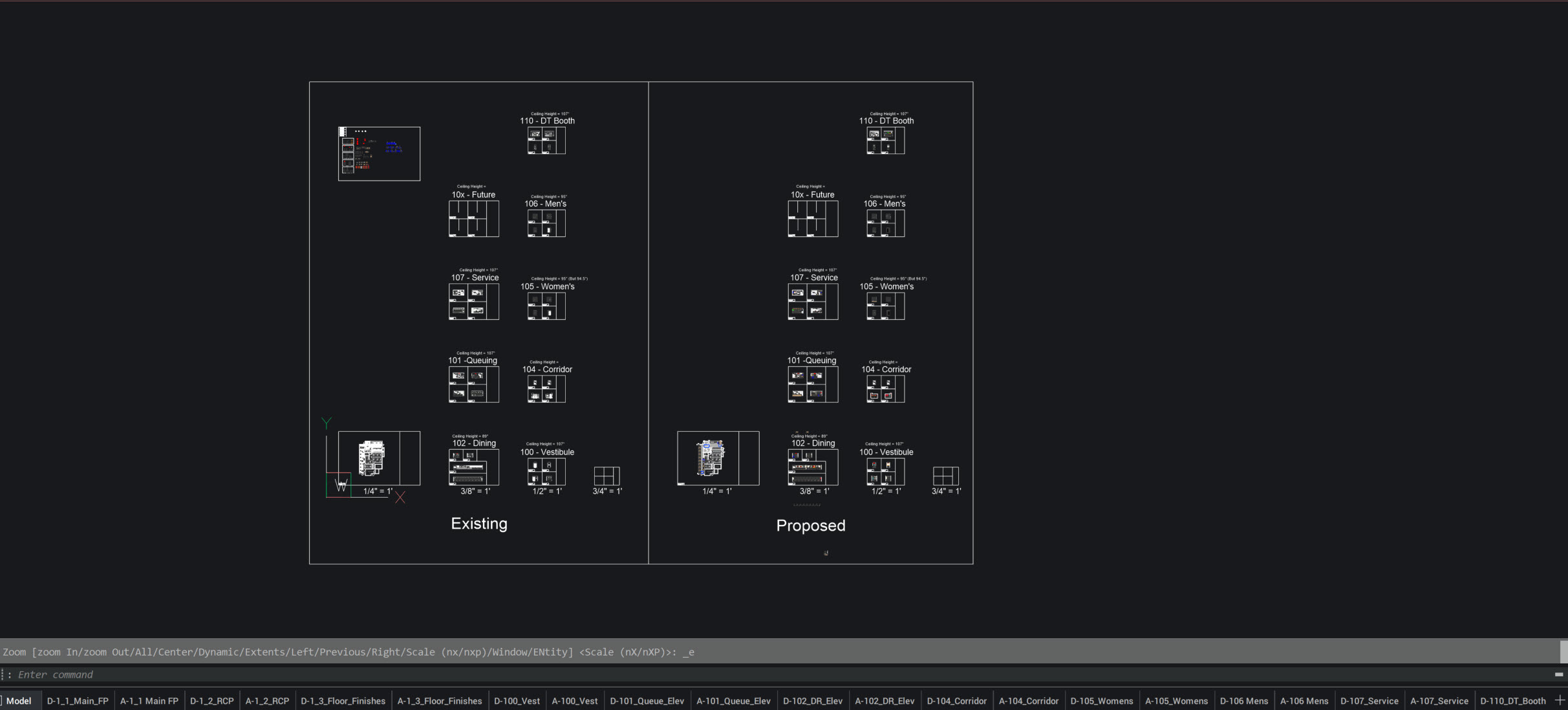
The attached image is a screenshot showing how I have my Model Space set up and it also shows many of the Layout Tabs I have. As you'll see, I've separated things into two different sides, with the existing conditions and demo details all being on the left side and the proposed details all being on the right side.
I first created the existing conditions and then copied those various existing conditions over to the proposed side and then modified those existing details as necessary to create the proposed conditions.
I basically have four views on each of my elevation pages, with one view looking North, one view looking South, one view looking East, and one view looking West.
For the main floor plan, the reflected ceiling plan, and the floor finishes plan, I have drawn those all directly on top of each other and I just turn on and off various layers to create the view of each plan that I want.
While I have many questions for you industry experts, I've already written a novel here, so I'll stop for now and let the roasting begin.
If any of you know of any YouTube videos that go into detail on how professionals set up things in Model Space for 2D drawings, please provide some links. Also, if there are any example .dwg files out there anywhere that are from safe and reputable websites that won't infect my Windows PC if I were to download and open them, please provide those links. If any of you are willing to share your own example files with me, that would be great too.
I realize sharing my .dwg would likely be the easiest way to show you all just how wrong I'm doing things, but it currently has some sensitive information in it that I would have to scrub first and I'm hoping the attached image gives you a good enough understanding to get this discussion started.
Comments
-
Just me I would start using layouts, once you get the hang of them you will nevr use Model again when it come to plotting final plans. In layouts you can scale views as well as the direction you look at objects, ie elevations.
The 1st simple step is have a master layout, this would have your title block in it, located at 0,0 for convenance, and true size at 1:1 scale eg a A3 metric would be based on a 420x297 size, with allowance for plot limits.
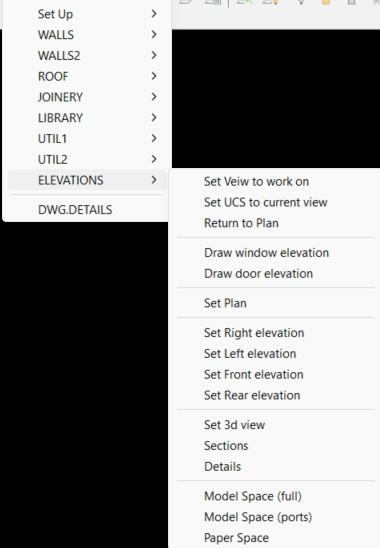
You can via lisp and a pop menu have the options all set up. Make/copy new layouts. You can pick a point in model, then make the layout with the correct scale in a viewport. Same with say a layout with multiple viewports, choose a Viewport for model display.
Re day to day stuff have a think about something you do all the time maybe repeat in a dwg and look at turning it into a lisp. One client 3 hours for a big dwg to be modified manually around 2000 changes, it takes 2 minutes now.
Outside sourced dwgs again a lisp can help setting up layers etc to the way you want it.
Cooment one Plotting yes a lisp just click on correct one and watch the prints come out, did 88 in one go for a project. Pdf, Printer or Plotter.
Have a look at attached Word doc. Some free some a small charge as they have to be customised to your CAD setup.
This image has 130 lisps behind it.
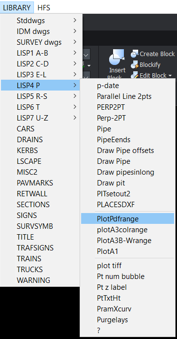
Another package menu's.
 0
0 -
Howdy DIY_Guy,
I hope this helps. My only claim to being a professional is that I get paid to produce drawings!
I've been using AutoCAD since R14 and switched to BricsCAD about three years ago. I've attached both a DWG and PDF for reference.
As you've mentioned, there are many different ways to approach drafting workflows. I've been using this particular method for the last 10 years with the same company. I'm also self-taught, so I can't claim it's best practice, but it has worked well for me.
Interestingly, the builders and engineers I worked with previously didn't use layouts at all. I find that combining viewport layer freezing with layouts helps keep everything coordinated. For example, if walls move on the ground floor plan, it's much easier to identify and update any affected elements on the upper floor.
My workflow is to draw everything in Model Space, then use layouts and viewports to control what is shown. I generally start with layer states built into my template, such as A-GF, A-UF, etc., and then make any viewport-specific adjustments as needed.
For plotting, I've changed Ctrl + P to use Publish rather than Print, as I generate a PDF every time I plot. I'm sure there are more advanced workflows available, such as Sheet Sets, but this approach works well for me until I take the time to learn a better system.
Like Alan mentioned above, I also use several Lee Mac LISP routines. I prepare sales estimates as part of my role, so having quick access to lengths, areas, and other measurable data is extremely useful. The LISP routine I use most often is Length & Area Field ( ), which I use to automatically populate areas in tables.
I work metric, A3 size sheets as standard, you're welcome to export any of the blocks in the dwg if it helps you get setup. I've attached the DWG file (with the client information removed) and a PDF showing the output generated when I publish. I also use custom properties to fill in my titlesheet, this is something I've never seen anyone else use (type "dwgprops" to view/modify). If you have any questions, comments, or criticisms, please don't hesitate to let me know. I'm always happy to share what I've learned and learn from others in return.
0 -
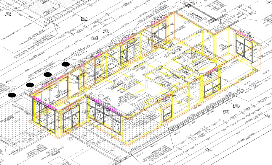
@Monday interesting dwg, a couple of suggestions, I have Draw walls, windows and doors. One advantage is that they have inbuilt clean up options like "Tee" junctions where a wall meets another. have a look at the Cadarc menu, happy to discuss more. The elevations are made as the walls have a "Thickness" and windows cut the walls. You can actually do a walkthough.
 0
0 -
Basically, you draw everything in model space. Then, the title block and notes go on layout tabs, where the title block is at its real-world size when you print it.
In model space, you only draw the house (or whatever) once. But, you put electrical on one layer, plumbing another, and any furniture or fixtures on another, etc. Then on each layout tab, you go into the viewport and choose what layers show or are frozen. You can also change the color. I sometimes go into a viewport and select all layers, and set them all to black in the viewport overrides.
It is possible to put dimensions in the layout tabs as long as your dimassoc variable is set to 2. That will make any dimensions in the layout tabs automatically scale its value to the scale of the viewport. It makes modelspace a lot cleaner, and can dramatically reduce the number of layers you have. BUT I have not found it to be reliable for a drawing that continues to be worked on. This is because it is easy for a dimension to become disassociated, and "forget" what it was dimensioning. And if you are working in modelspace you may not notice this. So when you print your revised drawings any disasociated dimensions may show the old, incorrect, value.
-Joe
0