Tin Surface not stepping on Z axis

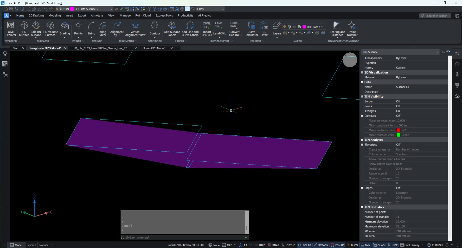
I'm working on a model of a building site with 120 houses, trying to make up surfaces of each plot to create a reduced dig surface for the excavators.
Each plot is broken down into the dwelling, driveway, grass area and concrete, each of which needs different reduced dig levels for the required fill to end up at the correct levels.
I have all my boundaries created of each part and all are closed, but when I try to tin the surface it seems to ignore Z values on over lapping lines (Attached a picture so you can see what I mean).
I've tried adding breaklines, points, creating the TIN from points, breaklines and every combnataion I can think of really, but cant get it to create 2 seperate 'platforms' while still being the TIN one surface, but it always seems to not count in 2 points on the top platform.
Any ideas which setting I havent turned on or have set incorrectly?
Comments
-
Hello.
There should be no overlapping points when creating a TIN surface.
In a standard TIN surface, a 90-degree vertical drop is not possible.
A TIN surfaces requires unique X-Y coordinates for every vertex and cannot stack two points with the same X-Y and different Z values.A solution is to slightly move one of the overlapping edges, so that there are no overlapping points when creating the TIN.
0