Efficient way to model slabs with multiple slopes (revisited - I read the older post on this topic)

I'm currently modelling a building from the ground up. I'm working on the slab on grade. The slab has multiple slopes owing to about 6 difference areas each draining to a separate catch basin. I need advise on how to model this efficiently. I've reviewed a previous post that had some good solutions, even a custom LISP one user posted. I don't need something equal to Revit's slab modelling capabilities, even a method that takes double the time would be okay (and I'd hope I can make-up the time elsewhere). So far any method I try is quite a bit slower. So much slower that it's pushing me into the area where the lost time would be more expensive that subscription fees :-( . I wonder if there's something new/better compared to the previous post and the tutorials I've been able to find.
To summarize: I need a slab modelling method that is no slower than 2x Revit's; It needs to be something I could teach a 3D modeler of an average skillset (this means no rapid keyboard mashing and memorizing a complex string of commands/options); and I need to have a consistent slab thickness, I don't want to just taper the top surface and have the overall slab thickness change (I want the slab to look correct in sections). Any insight into how to achieve this would be greatly appreciated!
I'm actually on my 30 day trial. I'm hoping I'm able to get BricsCAD to work for me as I'm a LISP programmer. I thought LISP and BIM together was only a pipe dream, so of course I'm going to give BricsCAD the college try. So far the 2D and (non-BIM) 3D are awesome. I'm still not sold on the BIM capabilities yet but still have lots to learn. I'm currently modelling a previous project to see if the switch is feasible, or if I have to stick with Revit.
Thanks in advance for any insight!
Comments
-
I could easily tell you how to model 3d solids, its the same in bcad as acad. You essentially draw closed plines for each level, then extrude.
You set the initial elevation of the plines to set elevs, or lift after the fact.
I'm a cad/civil guy though, not architectural BIM. Can you explain the difference between a "dumb" 3d solid, and what revit does?
Of course, I mean is the revit thing parametric? BIM is parametric while 3d models don't know how they were made or what they are.
thx0 -
One thing that Revit has over BricsCAD (which may only be a lack of knowledge on my part) is the ability to set the elevations of the slab: For example, if one of my catch basics drops a couple inches, I only need to change one elevation point to update my slopes (the slab will have four slopes in some cases, each leading into the catch basin). To change the elevation points you'd just click one of the points and go from there. Now this doesn't always work smoothly, sometimes I have to fight to get the result/shape I want but I get there in a reasonable amount of time. I can also dictate the slopes based on a percent if I choose to go that route (this will depend on the project; sometimes it's a judgement call as I want the drawings to accommodate the constructor).
The 3D modelling in BricsCAD looks pretty stout. I'm confident I could 3D model the slab. It's just way slower. If I model the slab exactly as you describe I won't quite get the result I'm after if BricsCAD's extrude command behaves the same as AutoCAD's. I need a continuous thickness slab with seamless joints if that makes sense. I think I would first need to draw the polyline exactly as you describe, copy it down the thickness of the slab, then "loft" the two polylines together. I haven't tried this in BricsCAD yet so I'm not sure if it will work, and I know it'll be a bit slow.
Since you're Civil you're probably more familiar with the "Civil" tab. I have a feeling the feature I'm searching for exists there.
To answer your question regarding a "dumb" 3D solid compared to a "BIM Object": I can model a 3D slab in either Revit or AutoCAD (if I really wanted). The slab in Revit obviously has extended data attached to it. Both programs will spit out the volume. Revit also knows what "level" the slab is based on; I have more access to the material of the slab (a slab on grade will have a different concrete mix compared to my suspended slab - but you could theoretically do this in AutoCAD too, but you wouldn't be able to do an automatic quantity take-off); I can change the geometric and physical properties of the slab much easier than in AutoCAD (such as the thickness let's say, or add a topping within seconds); I can "tag" the slab automatically (this sometimes actually works like we want); and finally, in a perfect world, I can model a slab waaaaaaay faster in Revit compared with AutoCAD. Revit isn't without it's flaws however, sometimes stuff just doesn't work like it's supposed to. One last thing I will add is that Revit allows me to add custom parameters. For example, I can add a custom parameter for the type of reinforcing in my slab on grade (there usually isn't any extra top steel, just a grid chaired at mid height). I can get my rebar quantity (other than the diagonal bars at openings/columns/corners/etc... but I can just account for this by adding a factor to the main steel) without having to actually model any rebar by using a custom parameter.
With schedules/Bills of Materials, I can either use my slab's material to separate it, or the level it is on. This is important more when I get into the suspended concrete work. In a concrete tower I want my concrete volumes separated by levels, even if I'm using the same concrete mix. I don't want materials named "level 1 concrete for columns, level 2.... etc..." or else my schedules look like garbage. So it's nice that the program knows what level my object is on.
I haven't gotten far enough along in my BricsCAD learning to know what the program is capable BIM-wise. I'm hoping to achieve results similar to those described above of course.
I hope that explanation was okay, it's been a long day ;-)
Cheers!
0 -
Can you add a link to the 'Older post' you refer to in the topic title?
It would also help if you explain what you start with. Is there a terrain model? Is it a solid? ...?
0 -
Here's the link to the previous thread:
https://forum.bricsys.com/discussion/34262/modeling-sloped-slabs#latest
Let's say I start with a 2D CAD file. Sometimes I'd be given slopes, sometimes I'd be given elevations (preferred, so that I can dictate the slopes).
0 -
Maybe this will work for you:
- Create 3D faces to model the terrain.
- Create regions from them.
- _DmStitch them together to form a surface.
- _DmThicken the surface to get the slab.
0 -
I do not have Revit so cannot compare the speed of its methods. The advantage of BricsCAD is that it allows so many ways to tackle these modeling problems, as evidenced by the variety of good ideas posted so far, regardless of whether the objects are classified as slabs, walls, roofs, or anything else.
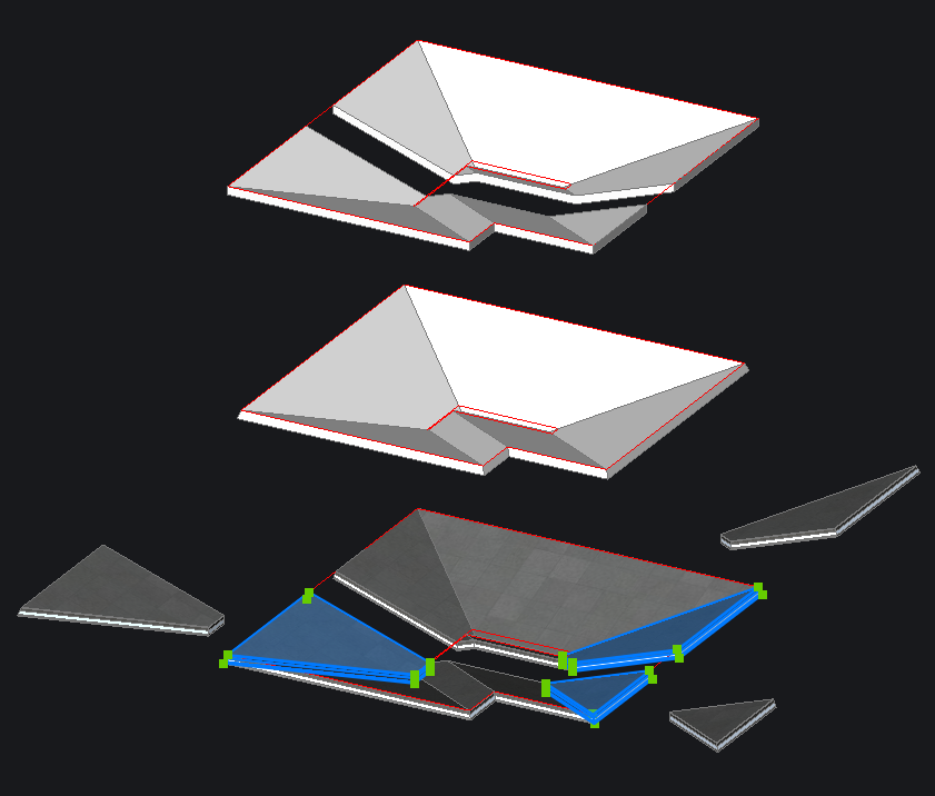
My approach was to loft between two closed polylines: one delineating the slab perimeter, the second offset inward towards the basin and translated in z to the desired elevation. Use offset to make the inner polyline have the same number of segments as the outer polyline, to ensure parallel edge pairs, and therefore planar faces, in the resulting loft surface. From here I tried three techniques:
- Select the lofted faces as a set and DmExtrude, using the Direction command option to lock extrusion to the vertical z dimension. I closed up the hole in the center with LConnect and DmPushPull. I sliced the resulting solid in two just to show the uniform extrusion height in the attached figure (upper solids).
- If you need uniform thickness for each slab facet rather than constant height, then use DmThicken instead of DmExtrude. The outer edges come out normal to the upper faces, which is how I left them in the figure (middle solid). You could either slice the edges off with vertical planes, or extrude a bounding solid down from the original perimeter polyline and Boolean intersect that with the thickened solid.
- Methods 1 and 2 result in a single 3D solid. For applying BIM compositions, its better to have each facet a separately thickened solid. Repeating DmThicken on multiple selections to achieve this took only a little longer. I did need to clean up the intersections a bit, but LConnect made quick work of it, only getting confused where three facets intersect in a tight spot, where I did resort to some slicing and push/pulling. I applied a multi-ply material to show how neatly the BIM composition works in the figure (lower solids), sectioning again with a few copies pulled out to show the individual entities.
0 -
I think the secret is to just model each sloped part separately.
And it depends if you want to slope the whole Solid,
or just its top Face.From there,
in Direct Modeling, (easiest by Transform Gizmo)
1. you can just select a single upper Edge and move it up or down
2. you can rotate a whole top FaceBy 2.,
Rotating Faces, you can also adjust slopes of complex
(non parallel Edges in top plan) Slab Elements,
by rotating about different edges after each other,
until you reach the final slope direction.
I did this once in Vectorworks for a stone walkway
to follow the terrain.In Direct Modeling you could also just select a single Vertex
to manipulate the top Face only.
(To create a slope not aligned perpendicular to an Edge)
AFAIK Bricscad will keep the Face planar in all circumstances.And as shown there are lots of other ways to to model or manipulate
to get the result.0 -
@KeithsCADServices said:
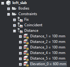
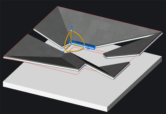
...I only need to change one elevation point to update my slopesBricsCAD BIM lets you create parameters and impose 3D constraints. As examples, you can constrain or parameterize the thickness of all the slab facets, you can impose coincidence on adjacent edges, and you can fix the position of perimeter edges. Then you can manipulate one piece and the others adjust accordingly per the constraints.
In the model image below, I've used the manipulator to move the blue facet over, and the adjacent solids deform to follow it. (For illustration sake, I did not apply a coincident constraint on the adjacent edges in the upper right valley, so that facet stayed put while the rest peeled away.)
For your application, you can make a parameter to define the elevation of a lower edge relative to some reference plane, and if you change that value, the model updates automatically.
BricsCAD can do those other BIM things you mentioned (schedules, BOM, custom parameters, etc.) but I am still learning those tools myself, too.
 0
0 -
Got it, so its not a flat slab. You would now be in the world of modeling a civil engineering triangulated surface.
You would then turn the triangles to 3d faces, extrude to get solids, and union to get one big solid.
Civil surfaces are modeled with "breaklines". That is really any 3d line and points too. Those things act like ribs for an umbrella, and the tris stretch to connect them by connecting the closest points.
Lofting does a similar thing, but is limited by sections in order - no good.
For a slab, you would make one 3d pline around the edge, with correct elevations at each point. Then draw any creases with elevations.
Then turn into TIN surface. You likley need a 2d edge also to trim out the tris that "reach" accross corner to corner, if you don't have a convex outline.
Steps are modeled with slightly offset 3d plines. You cannot have true vertical faces in TIN surfaces, that would be undefined.
You could model in pieces and union together later to get perfect vert steps though.
So your workflow is:
1) Make the 3d plines
2) Make the TIN surface
3) explode to 3d faces
4) extrude thickness
5) union
6) to edit, erase solids, mod 3d plines, and start back at 2Making and editing the breaklines is the big deal here. Civil3D tried to make that easier with feature lines, but blew it.
Civils do not put 3d grade breaks at same location as horizontal change points. We might, but not at all of them.
Again, we wrote our own tool for that, called a "3D alignment" which apparently inspire bricsys, but ours is a different creation and editing tool.
Anyway, I don't know the bcad surface tools well yet, but these are the concepts people in acad world have done forever.
Civil3d even has a surface to solids tool, but only works well on low tri count surfaces. Unioning many solids is not fast when you do too many.0 -
I did a quick example, where you have 3 basins, and some seams that divide the slab into runoff zones.
Of course, this is a whacky example, but shows there is no limit to where 3d breaklines can be.
Plan view of 3d linework, created with our 3d alignment tool (not one in bricscad):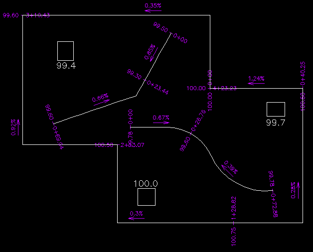
Then triangulated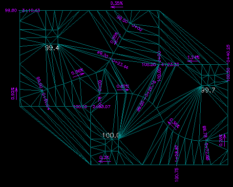
then with 0.1 ft contours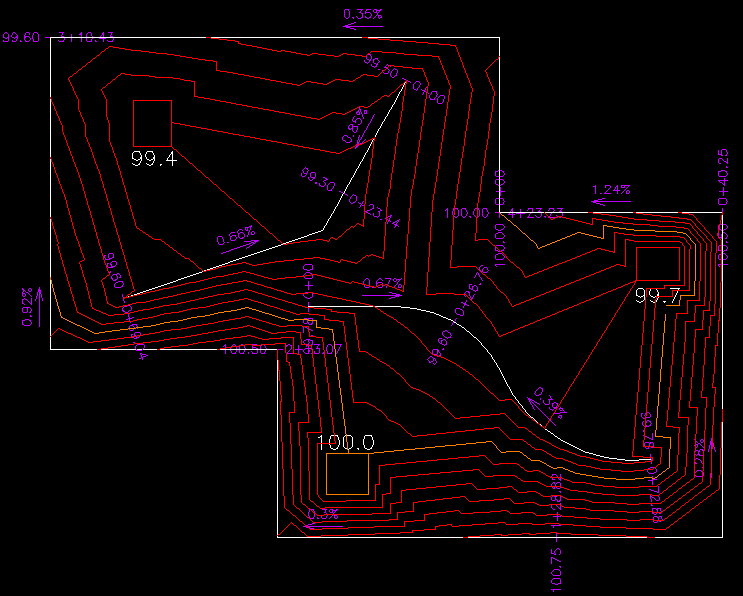
then turned into solid
Note that the union at the end did not work, gave some error. So this rabbit hole does not end well, LOL, but its how TIN surfaces are done.
I could get around that error if I wanted using a program. Just mentioning the union step is a bit finicky.
thanks0 -
Thanks for all the great feedback everyone! ScottS And James Maeding: I have never gotten such thorough walk-thru's in paid technical schooling let alone for free on a message board ;-) . Thanks for going into that much effort. I'm now 100% confident I can create the slab, and now I just need practice.
I should mentioned that Revit's systems aren't without their flaws either. Sometimes I will model the slabs separately due to too many lines appearing on the slab. Or use other work arounds. All the hassle reminds me that I used to do stuff like this in 2D; I would utilize a handheld calculator and piece of scrap paper just as much as the CAD program itself. Things would end up being exactly how I wanted them, but this also meant I had to manually create the sections (which I didn't mind). This would probably still be my method of choice. Problem is when you go on vacation and the person taking over isn't quite as keen on following the old 'manual' methods.
James: I saw the "TIN" surface button under the "Civil" panel and thought that maybe that was a possible solution. Prior to today I had absolutely no idea what exactly they were. By "3D Breakline" do you mean a line where the slope changes? Including (but not limited to) the "ridges" that separate each catch basics drainage area? Looking through past plans, most plans show something more like ScottS's example (flat slopes), but the actual "as-built" ends up closer to a "TIN Surface". This has a lot to do with the quality of grading the base for the slab, and the concrete finishing on the slab itself.
ScottS: I haven't even touched the "BIM" features of BricsCAD yet. I'm hoping to at least get well-enough acquainted with the programs features to know whether the program is a Revit alternative, a Revit beater, or better left as a 2D/3D CAD software program. If my memory serves me correct I recall that Revit was an up-hill battle. Many claim the program is easy to learn. But I never heard the best 3D modelers claim such. I expect BricsCAD to be a bit of a challenge as well. I am also struggling to find good tutorials.
Thanks once again everyone!
0 -
@KeithsCADServices Happy to help when I'm able, and get to learn more myself in the process. Thanks to your question, I got to explore 3D constraints more, and thanks to @James Maeding I have a better appreciation for how TIN surfaces can be useful in architectural models.
The wizards at Bricsys create features faster than the tutorials can keep up, certainly faster than I can watch them. Recently, though, @Michael Mayer shared here a very informative new series: BIM Academy.
0 -
@KeithsCADServices said:
James: I saw the "TIN" surface button under the "Civil" panel and thought that maybe that was a possible solution. Prior to today I had absolutely no idea what exactly they were. By "3D Breakline" do you mean a line where the slope changes? Including (but not limited to) the "ridges" that separate each catch basics drainage area? Looking through past plans, most plans show something more like ScottS's example (flat slopes), but the actual "as-built" ends up closer to a "TIN Surface". This has a lot to do with the quality of grading the base for the slab, and the concrete finishing on the slab itself.Hey there,
A 3d breakline is a 3d line whose segments go up and down as needed. Its not a lightweight polyline, that is at one elevation.
Those cannot generally be made efficiently using basic bcad commands. In your case though, I bet you could as you don't have curves involved.
The things that make TINs actually derive points from the breaklines, but then restrict triangles from crossing them too, which is what civils want.
The world of TIN creation and editing, once you have the 3d breaklines, is done really well by most civil software. Bricsys is kind of new to it and I don't know all its commands yet. Most civil software does not make the 3d breakline creation easy. Its either complicated when using road alignment data, or cumbersome when doing little stuff because it forces an elevation at horizontal vertices. We did our own tool on that.0 -
Attach a workflow you could use with the new BricsCAD TIN commands (requires V20 Platinum or greater). The created TIN is associative to the
PLINEbreaklines, so at this stage you can modify the polyline and the TIN will update.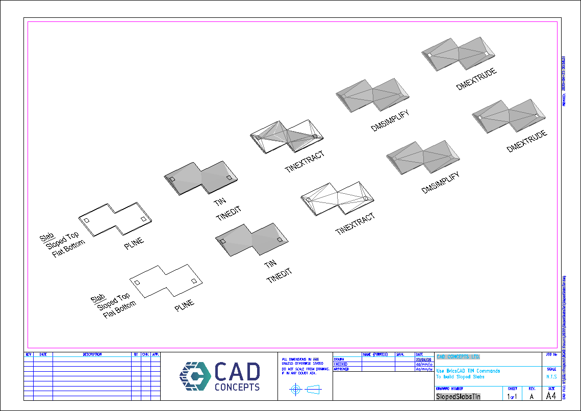
The commands used are listed under each step, and in the PDF you can jump to the
HELPsection for that command.edit noticed a typo on the drawing. The bottom row is a slab with a sloped bottom & top. The top row is a slap with a sloped top face and flat bottom.
Regards,
Jason Bourhill
BricsCAD V20 Ultimate
CAD Concepts0 -
@James Maeding said:
a 3d line whose segments go up and down as needed. Those cannot generally be made efficiently using basic bcad commands.Wouldn't a bcad 3DPOLY do it?
0


